Tool/software:
Hi,
I am trying to develop a driver for the ADC on this board for my specific platform (gaisler).
I was able to install the GUI SW, start up the board and also capture a signal that I have on one of the input channels. So far so good.
Now I would like to keep the setup with that input signal, but not use my PC to communicate with the ADS1278.
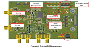
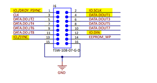
I have been trying to read the ADC data over the SPI interface over the jumpers on J6. Here I have connected SCLK, MISO and GND to the corresponding pins on my own platform.
My issue now is, that i do not get any data. Apparently the SCLK line gets pulled high by the board (if i measure the clock line on my own HW, I can see the SCLK that is supposed to drive the communication, once i connect it to the ADS1278EVM board, it is just high).
Therefore I wanted to ask, if you maybe could provide me with a guide on what I need to do and what I need to consider, to be able to use the ADS1278EVM-PDK without the PHI Board, so that I can develop a driver for it on my platform.
Thanks a lot in advance!
Kind regards
Hello Tanja,
Welcome to the TI E2E community.
In order to use the ADS1278EVM board with an external controller, you need to remove the PHI board, otherwise, the digital lines will be driven by the PHI board preventing correct operation with an external MCU.
1. Provide +6V on J10 from an external bench supply.
2. Move jumper JP1 to the 27MHz position, this enables the on-board 27MHz oscillator.
3. Move jumper JP2 to the EVMCLK position, this selects the on-board 27MHz oscillator.
4. You may need to install jumpers on J4, depending on the mode of operation that you want to use. Assuming you will configure for high-speed, SPI, TDM, Dynamic, then you will need to install jumpers on MODE0, MODE1, FORMAT0, FORMAT1, and FORMAT2. CLKDIV should remain open (high).
For the SPI connections on J6:
1. MISO -> DOUT1
2. SCLK -> SCLK
3. Connect DIN to GND, do not leave floating.
4. Connect /SYNC to an IO pin on your MCU (needed for robust power-up reset), or tie to IOVDD for test purposes.
5. Connect /DRDY to an IO pin your MCU. This is an output from the ADC, indicating when data are ready to be read. The code should monitor this pin (polling or interrupt) and only transfer data after a falling edge (Figure 77).
Regards,
Keith Nicholas
Precision ADC Applications
Thank you very much for the quick and detailed answer!
This resolved my issue (tying /SYNC to IOVDD and setting the FORMAT jumpers right did the trick).
Kind regards