This thread has been locked.

If you have a related question, please click the "Ask a related question" button in the top right corner. The newly created question will be automatically linked to this question.

AMC131M03: CRC issue

Part Number: AMC131M03
Other Parts Discussed in Thread: ADS131M04, , SN74LVC1G17, AMC3336, AMC1336, AMC0386, SN6501, UCC33020, ADS1204, ISO6761

Tool/software:

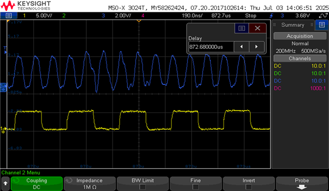
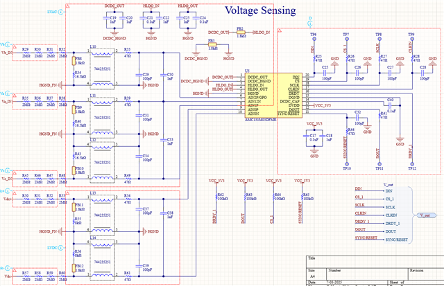
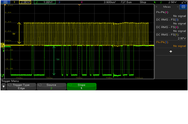
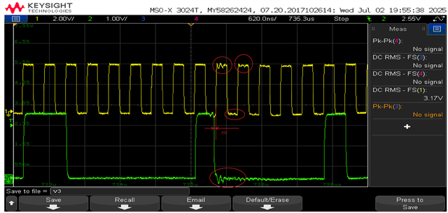
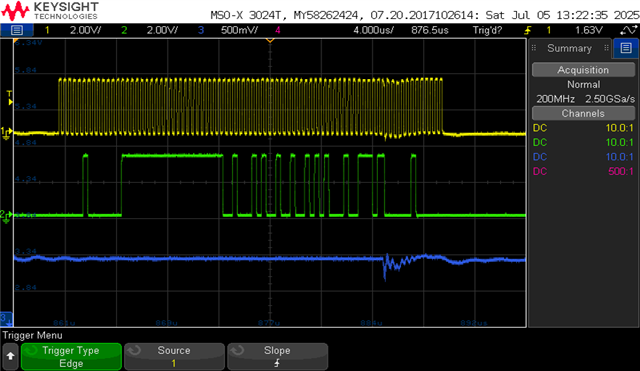
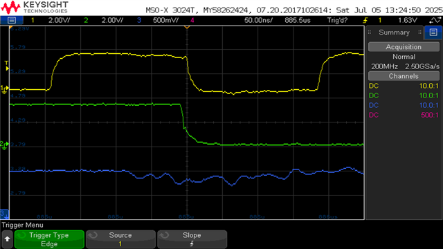
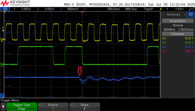
Hi im using AMC131M03 and ADS131M04, im having an issue in crc, in what are the ways the crc mismatch error can come, input crc im not using, im using only output crc received from devices and im using ccitt  crc polynomial. my spi clk is 5.3mhz, mode 16bit , clock in 8mhz and osr is 64ksps. so in my case crc is not matching when enabling the switching (PWM) for the converter. during that time my crc is half of the time not matching what could be the reason for crc mismatch. im reading the data every 50us, with single spi bus of two devices, i dont know in what are the ways that crc mismatch can happen. after finishing the parameter configuration initally 1- or 2-time crc is not matching after that it is perfectly fine for both the devices. when started switching it becomes crc error and my switching is based on the values reading from spi .it is any timing issue or clock issue or any noise affecting.

    if data is not ready im reading the data during that time the crc mismatch can happen or not?. and im not usng drdy pin due to interuppt handling, so every 50us im reading the data. can anyone suggest or helpme to findout why crc mismatch is happening. why it is happening in during first time reading after parameters configuration also. 

regards, 

srinath

  • Hello Srinath, 

    The AMC131M03 family has multiple CRC mechanisms described in the datasheet. I understand it the way that you are talking about the CRC that the microcontroller receives after SPI transmission.  Since you refer to PWM, I also assume that you talk about a power conversion application.

    If you have a problem with the CRC when you enable the PWM the problem is likely in the signal integrity of the SPI interface. In general, I recommend adding a 10 ohm resistor on SPI lines and 15pF capacitor on both ends of the signal trace. 

    Please also make sure that the CLKIN signal  is clean without any reflections or glitches. Some microcontrollers are not able to drive the CLK signal fast enough. Below is an example of the CLK when the MCU is not able to drive a longer PCB trace with the capacitive loading. 

    /resized-image/__size/320x240/__key/communityserver-discussions-components-files/73/pastedimage1749541539081v1.png

    Here is an example for the very same signal with SN74LVC1G17:

    /resized-image/__size/320x240/__key/communityserver-discussions-components-files/73/pastedimage1749541706525v2.png

    Summary:

    • Add 10 ohm serial resistors with all digital signals (DIN, DOUT, CS, SCLK, CLKIN). 
    • Place 15pF capacitors between the above mentioned signals and ground DGND. Do it as close to the MCU and AMC131 as possible
    • Make sure that the MCU can drive the CLKIN without too much distortion. Add an AC termination circuit if needed (100 ohm, 220pF).

    PS: Suggested values are rule of the thumb, you may still need to adjust the values to match the PCB design.

    Attached is a PDF with the key suggestions. I created this overview for isolated modulators but the logic and principles apply to AMC131M0x as well. 

    /cfs-file/__key/communityserver-discussions-components-files/73/modulators_2D00_interfacing.pdf

    Kind regards, 

    Jiri Panacek

  • Hi Jiri thanks for your response.

    CLKIN U have mentioned is spi clk or osr CLKIN from mcu. since spi clk is fine only, my sampling CLKIN of 8mhz looks like a sinewave not as square wave.

    And we have an 47ohms and 100pf capacitor are added on the circuit. on all the lines of spi. we have two  pcb boards, mcu and sensing board, from sensing board to mcu the signals were transferring through ethernet cables. thus, in ethernet cable these spi lines miso, mosi and spi clk will be transferred as a differential pair signal, then again will be changed to single ended signals in the respective areas. 

    i have reduced the spi clk to 2.65mhz, clkin is 7.7mhz and AMC131M03 time will be 30us and ADS131M04 time is 35us. after changing this again i turned on the pwm for 4 seconds. first time i got 7 times crc not matching in AMC131M03 and second time i got 3 times crc not matching in AMC131M03. during these two times ADS131M04 is ok i havent get any single crc error and during these conditions. all the time my crc is matching in both the devices without pwm and with pwm only i got crc error for some times.

    before when i run the pwm for 50ms itself i will get 150 - 200 ticks of crc error on both the devices as per my first question.

    what to do for this crc error.

    regards,

    srinath

  • Thanks for the clarification Srinath, 

    regarding the CLKIN - I mean the clock for the delta-sigma modulator inside the AMC131M0x device, not the SPI clock. 

    I personally assume that if the CLKIN signal looks more like a sineweave, it is not a a big problem as long as there is not any glitch around the logic level thresholds. The CLKIN input does not have any de-glitch filter.

    Could you share a part of the circuit diagram and the CRC routine?

    I worked with the AMC131M0x quite a lot and never encountered a CRC problem. 

    Are you also reading and checking the status register? Are there any faults reported? 

    What would be interesting is plotting (or saving) the ADC data when the CRC problem happens. I am genuinely interested if the complete frame is corrupted or just the CRC. 

    I still bet that the problem is in the signal integrity. What kind of differential driver do you use for driving the ethernet cable? How long is the cable?

    I know this is a lot of questions However, without seeing waveforms and confirming that both, the SPI master and slave, see the right waveform that is not distorted providing an advice is difficult.

    Best regards, Jiri  

  • One extra thing - Can you turn off the power stage (any high voltage) and enable the PWM again?

    In case you see the problem again erven without the HV present in the system, you might have a cross-talk between the PWM signals and the SPI signals.

    Alternatively, there could be a race condition in the MCU (e.g. an interrupt triggers in the middle of the CRC calculation, etc.).

  • Dear Jiri,

    CRC ERROR FRAME.pdf

    Thanks for your reply. We are configuring ADC in 16-bit mode, 8 ksps, DC-DC enable. 10 bytes data that we are receiving is 0407 FF6C 38D0 C082 23FF. CRC is not matching. Waveforms of SPI clock and DOUT (MISO) is attached, captured right near the ADC. It looks data is received correctly on SPI bus. How can we move further? Looking for your help...

    Regards,

    Jitendra

  • Dear Jiri,

    Some more information on this issue:

        - CLKIN signal captured and image is below


        - Schematics is below


        - ADC values are also not correct (corresponding to analog input) along with CRC when the CRC fail event occurs. Till now every time it is ADC channel 2 whose data is not correct. ADC0 and ADC1 looks good.

        - In MCU, DRDY is configured as high priority interrupt and the SPI frame is read with the help of DMA so that no other interrupt interrupts the 10 bytes SPI frame

    We have tried with different values of bypass capacitors on DVDD pin but the issue persists.

    Is there any circuitry in the device which is sensitive to DVDD voltage and causing device to partially reset? We have observed little oscillations on DVDD pin, can this be an issue? How to address this issue?

    Regards,

    Jitendra

  • Thank you for providing all the data. Let me digest this and I will go over with with our digital engineer. 

  • Dear Jitendra, 

    first, thanks a lot for providing all the information. It does not happen every day that a customer asking for help provides clear and crisp data for analysis.

    I reviewed the material together with our digital engineer for the AMC13xM0x devices. 

    Based on the content of your buffer, (0x0407, 0xFF6C, 0x38D0, 0xC082, + CRC ) we also came to the matching CRC 0x8A7F. This confirms that your firmware calculates data properly.

    However, we identified two things, that are not clear to us and may indicate the origin of the problem.

    1. You power the device from DVDD = 3.3V. When I look at the SPI waveforms, it seems that the host controller uses 5V logic levels. This means the SPI clock signal is overdriving the pin. The digital signals have to stay withing DVDD, DGND range. Otherwise, it may cause unexpected behavior as the internal protection cells (ESD) open, cause extra current, etc.
    2. The second problem is in the CH3 data transmission. Even when looking at the previous waveform, that represents the complete frame, there is some unexpected voltage drop in logic levels. When I look more into the CH3 waveoform, I see that there the DOUT pin changes the level unexpectedly. (this can be an ESD diode triggering). 

      Our device changes the data (level) on the rising edge of the SPI clock coming from the SPI master. This is nicely visible in other DOUT changes, that the DOUT changes just couple nanoseconds after the rising edge of the SPI clock. However, in this example, the DOUT changes even before the edge comes. I assume that there is something wrong on the system level and this might be a result of the impulse noise. Could you also monitor the DVDD when this happens?
  • Hi Jiri,

    Thanks for your suggestions. As suggested, SPI CLK voltage reduced from 5 to 3.3V. Still the problem persists. As required below is the DVDD capture.

    Does noise at sync/reset pin can cause the behavior that you identified in point 2?


    Regards,

    Jitendra

  • Hello Jitendra, 

    do you have any explanation for what's happening with the power rail ? What starts the dip and the oscillations? This is a part of the waveform that concerns me the most. 

    Regarding the sync-reset pin:

    On first glance, I do not anticipate problem there. When the reset of the device occurs, the DC/DC converter disables and has to be re-enabled again. Also, the default configuration for the SPI frames would be 24bits.

    Actually, I did not ask before:

    How does the controller react to the CRC error? Does it indicate the error but continues with operation? Are the subsequent frames correct?

    In case you stop the firmware (e.g. assert), can you please check, if the DC/DC converter inside the AMC131 still operates? You can measure it across capacitor C19 with a multimeter. 

    We need to find out of the device resets (that would be also indicated in the STATUS register) or is completely confused and outputting wrong CRC. 

    I've seen the device resetting under harsh conditions but we have not been able to get a wrong CRC on the SPI yet. 

    BR, Jiri

  • Well, I've been thinking about that and I think I have a theory and some answers to my own questions (please check). 

    I believe that the device resets about the time I highlight with the arrow. The fact that last two bytes in your buffer are 0xFF and 0x23 are not a coincidence. The device sends 0xFF23 after the reset as mentioned in the device datasheet:

    Do you always get FF23 or 23FF when this happens? 

    I bet the DC/DC converter remains disabled after you detect this CRC error.

    What is puzzling is the fact that you get 23FF instead of FF23. Nevertheless, you also operate in the 16b mode whereas most of our customers (and my own designs) use the 24b mode. Normally, after the successful reset, the device requires some time before the new communication can start. However, if the reset occurs during the SPI transmission, also the device internally reconfigures SPI from 16b to 24b frame. I can imagine that there is some garbage, or a race condition, that results in 23FF instead of FF23 due to this transition from 16b to 24b frame. 

     It is now me wildly guessing but 0xFF and 0x23 are not a coincidence. 

    What you shall also try:

    • If you use the GPIO of a microcontroller for driving the CLKIN pin, try to get there a buffer such as SN74LVC1G17. It has significantly higher driving capacity than most of the modern MCUs. 
    • Make sure the CLKIN signal has 3.3V logic levels
    • Use AC termination if needed:
    • If your system has too much noise that is difficult to control, you may need to implement recovery mechanisms in the software. For example, in one of my boards used for extreme testing, I have counters for F_RESYNC, REG_MAP, CRC_ERR, RESET, FUSE_FAIL, SEC_FAIL, CRC mismatch, RST acknowledge, etc.
    • The noise and resulting ringing on the 3.3V rail shall be better controlled.  
  • Hello Jiri,

    Thanks for your suggestions.

        - Noise is coupling with power rail and we are looking into the possible root cause of this

        - We are running the power converter control based on the received ADC values. As soon as the CRC error occurs, we stop the control. We have not checked the output voltage of DC-DC in case of CRC error but subsequent frames return the status as 0x0407 which is same as the status received before CRC error. Chip select goes high and low again between each frame.

        - We will check the DC/DC converter voltage and let you know

        - 23FF or FF23 are consistent in CRC frames. CRC field varies and not same in case of error

        - We have RC filter on SYNC/RST and replaced C with high value of 100 nF and did not observe CRC error for sometime but this thing needs to be confirmed in full power conversion condition. Do you think that slight drop in the voltage of this pin can cause this issue?


        - Finally we want to use 24b mode but right now due to limited bandwidth available on SPI and intentionally slowing down of SPI to debug this error, we have switched to 16b mode

        - We will incorporate the suggestions that you have provided

        - Also, is there any 3 channel device which directly outputs the 3 HF bitstream of Sigma-Delta ADC rather than having integrated filter. 

    Regards,

    Jitendra

  • Hello Jitendra,

    unfortunately, I am running out of ideas what else to try. I must admit that I am running out of ideas. The Sync/Reset pin does not have any de-glitch filter and you're right that this might be a reason why you see improvement with 100nF cap.

    Regarding your second question:

    - We do not have a multi-channel input device with the galvanic isolation except the AMC13xMx that you've been using. For control applications, our customers use typically a single-ended device such as AMC1306 (current sensing) or AMC1336 or such. There are also devices with integrated power such as AMC3336 or AMC3306.

    Here is nice overview. Isolated ADCs | TI.com

    Please note that our latest device AMC0386 integrates the HV resistor divider.

    For isolated power, you can either implement devices such as SN6501, SN6505 or integrated DC/DC (example UCC33020).

    In case you would implement a non-isolated delta sigma, the ADS1204 is four channel. You could use a digital isolator for isolation (ISO6761)

    I hope this helps.

    Best regards, Jiri