This thread has been locked.

If you have a related question, please click the "Ask a related question" button in the top right corner. The newly created question will be automatically linked to this question.

ADS1148 whit 2,3 and 4 wires

Other Parts Discussed in Thread: ADS1148, ADS1248

Hello,

First of all, I wanted to thank those who make this forum possible,it  is helpful.

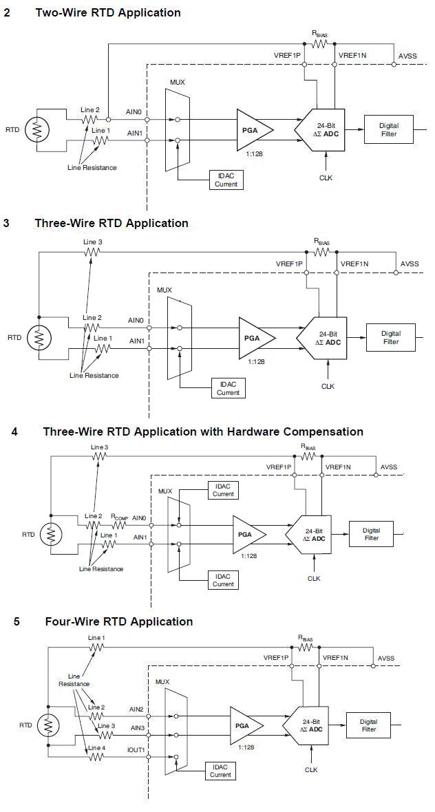
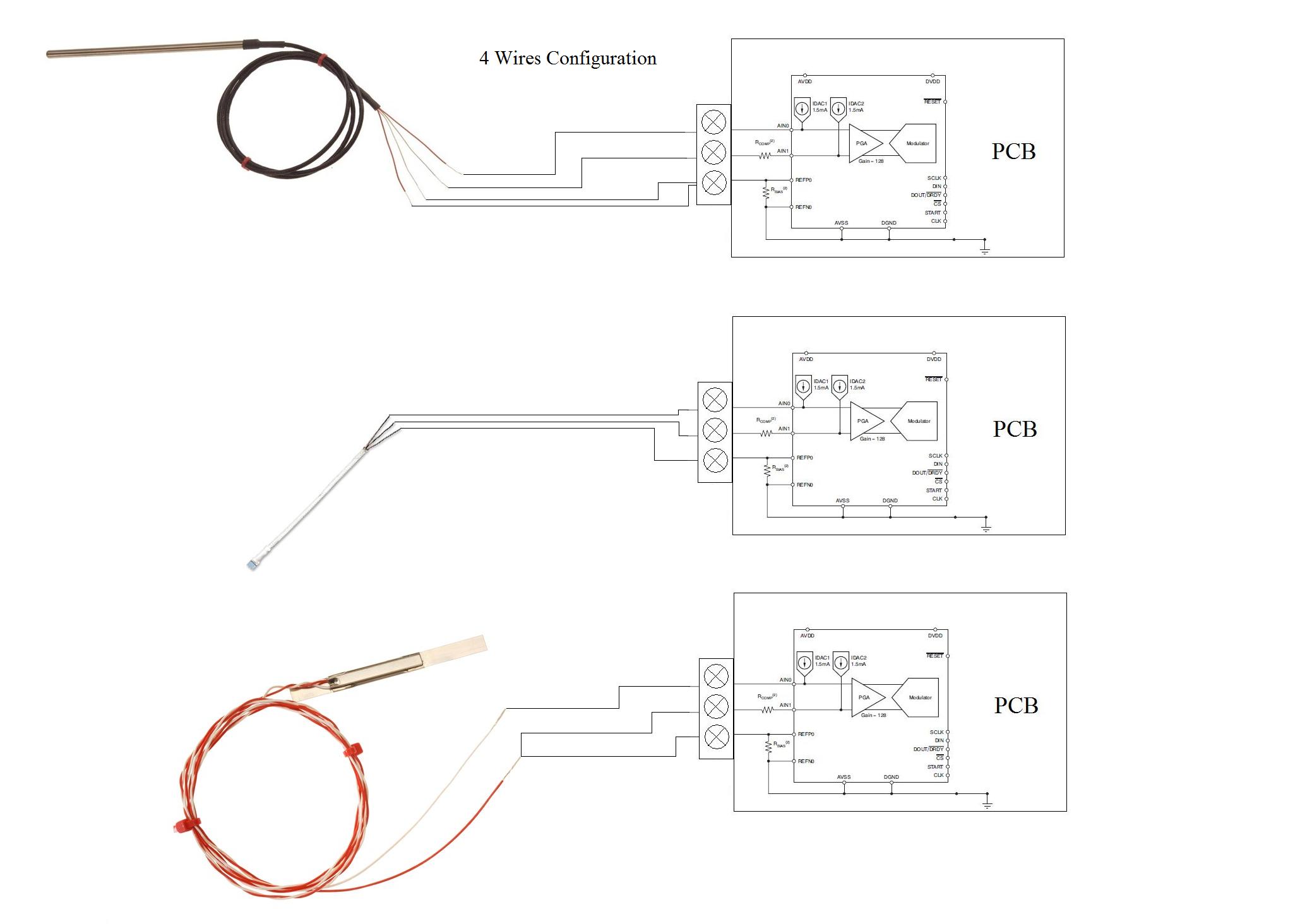
I am designing a device to measure temperature with a PT100 using the ADS1148. I would like my device was suitable for measures with 2,3 and 4 wires. I have several doubts:

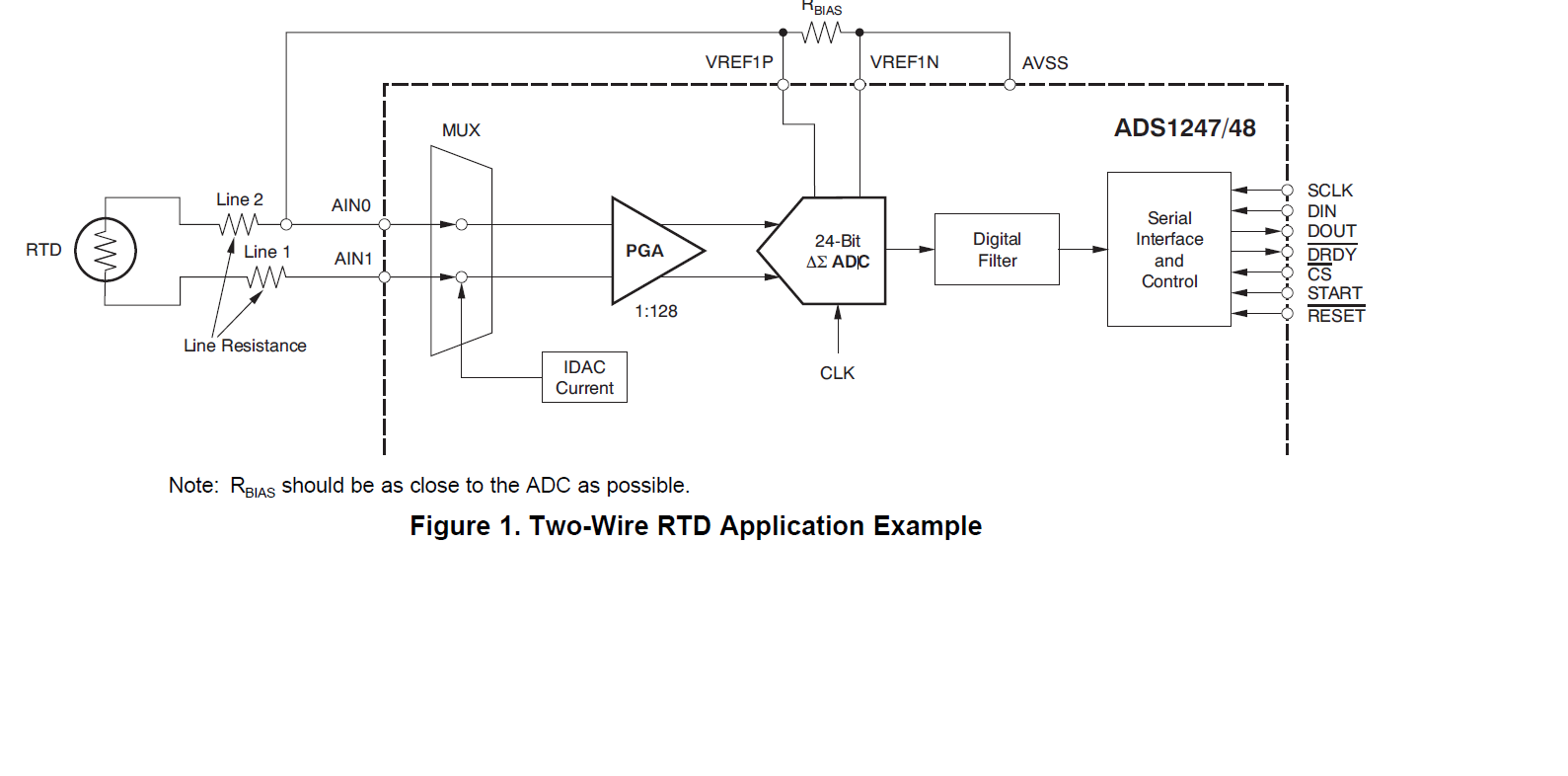
- is it better option use a big Rbias (25kohm), high PGA Gain (128) and low IDAC current (about 0.1mA) or viceversa?

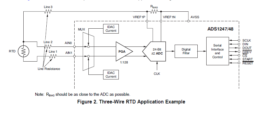
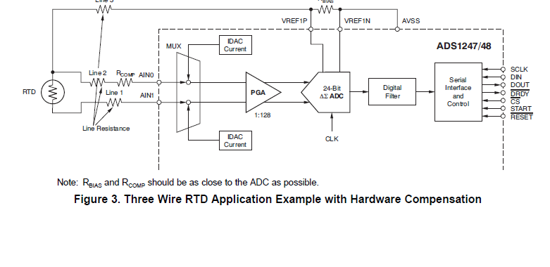
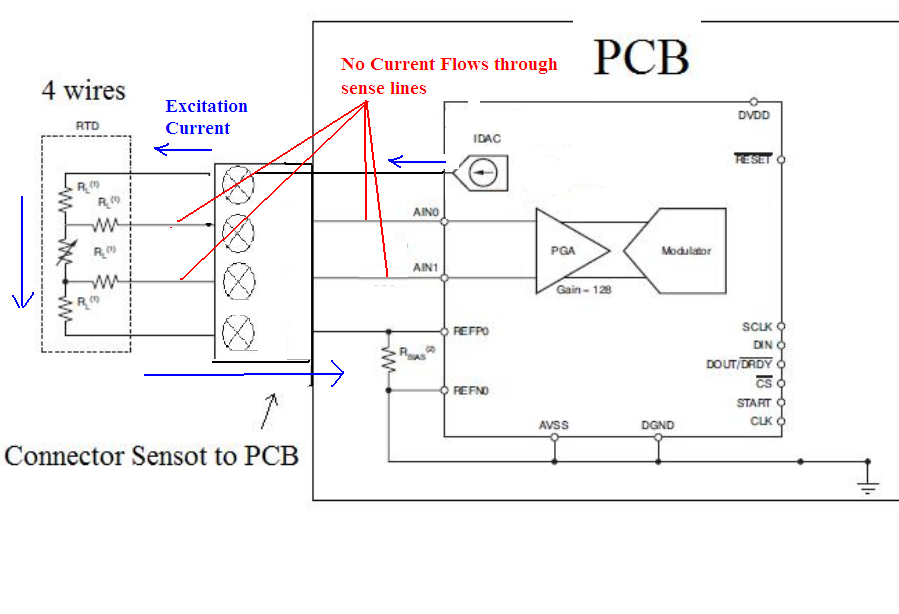
- What is the differnce between 3 wires using a Rcomp and 2 IDACS and 3 wires without Rcom and with 1 IDAC (figures 3 and 4). Is it I can place a smaller Rbias with higher IDAC and PGA gain? or to use all the full scale, because ADC (modulator) input varies between -1.25V and +1.25V instead of 0 and +2.5V (using AVDD-AVSS = 5V)?


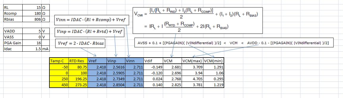
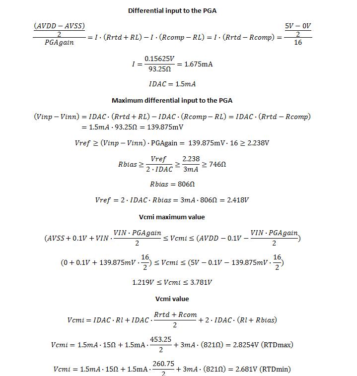
- VCMI for the circuits are:

2)  VCMI = IDAC*(2*RL+RRTD)/2 + IDAC*Rbias

3) VCMI = (IDAC*(RRTD+RL)+IDAC*RL)/2 + 2*IDAC*(Rbias + RL)

5) VCMI = IDAC * (2*RL + RRTD + Rbias)

Are correct?

Thank you very much

Regards

Andres

  • Hello Andres,

    When selecting the IDAC excitation current, the user has to account different factors, including resolution and RTD sensor self heating.  The larger the excitation source the larger the output will be making the output easier to measure and increasing resolution.  However with RTD sensors, the larger the excitation current, the larger the self-heating effects will be; which will add to the measurement error cancelling out improvements in resolution. Depending of the type of RTD element or probe used in the application,  dissipation constants may be in the range of 1mW/C to 60mW/C; therefore, the heat dissipation constant will vary greatly depending of the type of RTD probe used and the type of environment that will be measured in the application.  Some RTD probes tend to be large; and may be used to measure the temperature of a fluid.  These may tolerate larger excitation currents in the order of ~1mA with negligible effects due to self heating.  In contrast, RTD’s used to measure the temperature of gases tend to be smaller in order to have faster response times.  These smaller RTD’s will be more sensitive to self heating.  For these cases, the user could consider using a smaller IDAC current setting such as 100uA to avoid self heating and scale the RBIAS/Reference resistor accordingly. 

    The advantage of the three wire with hardware compensation is that the compensation resistor allows the circuit to completely use the input dynamic range of the device by adding a compensation resistor, RCOMP, in the second arm of the RTD. The voltage drop across RCOMP subtracts from the voltage drop across the RTD. The value of RCOMP is chosen such that it is equal to the RTD resistance at the middle of the temperature measurement range.  This allows for more headroom to use larger PGA gain and obtain more resolution.  The slide attached explains the advantage the Three wire with hardware compensation. Please attachment below. 
    Important Note:  Both the 3-wire and the 3-wire with hardware compensation use two IDAC currents...Please refer to figures 2 and 3 of application note SBAA180; also attached below. 
    Also, please refer to the link below to another forum post where the common-mode voltage is calculated for the 3-wire configuration with hardware compensation.
    http://e2e.ti.com/support/data_converters/precision_data_converters/f/73/p/193943/693044.aspx#693044
    Best Regards,
    Luis


  • Hello Luis,

    Thank you very much for your answer, it has been really useful to me.

    I have just done some calculations for a PT100 (from -50 C to 450 C) and I would like to know if they are correct. (I have attached the calculations)

    I would like to know if it is possible to use a 3 wire circuit with Rcomp, to connect PT100 with 2 wires and with 4 wires. In case of 2 wires, connect Rbias line with a sensor line using a small wire in the terminal connector (make a small connection between 2 screw terminals). In case of 4 wires, screwing 2 wires of the PT100 in the same terminal connector. You can see this connections on the attached image.

    I ask this question because I would like my device to be for all kind of PT100 (2, 3 and 4 wires)

    thank you very much

    Andres

    8168.calculos.xlsx

    2627.Differential input to the PGA.docx

  • Hello Andres,

    The calculations for the 3-wire example above are correct; and you explain them very clear.  Thank you.  The connections for the Two-Wire and Three-Wire shown on your post above are also correct.  One important thing to consider in the board layout is that the INP and INN board traces must be well matched when using the three-wire configuration 

    For the 4-wire configuration; it requires a 4-wire terminal connector.  In the 4-Wire configuration, the RTD needs to be connected through 4 completely independent/isolated wires and board traces; otherwise, in the drawing above, current will flow through the sense line.  Please see the 4-wire configuration below...The advantage of the 4 wire configuration is that the current excitation flows through a different path; and the sense lines connected to INP and INN have no current flowing through them.  Since the ADS1248 PGA input impedance  is very high,  only a few nanoAmps will flow through the sense lines and  the errors due to the series resistance of the sense wires is negligible. 

    Thank you and Best Regards,

    Luis

  • Hello Luis,

    Thank you very much for your explanation, It is very clear and useful.

    I would like to make a PCB to connect PT100 2 wires, 3 wires and 4 wires, using the same PCB circuit. Because of that, I would like to make a 3 wire circuit with Rcomp, because it is the most common PT100 configuration and I use all the full scale (0000 to FFFF), and then adapt the others configurations.

    In other words, converting 2 and 4 wires in 3 wires. For 4 wires configuration, connecting two wires together in the same terminal connector, and for 2 wires, making a small bridge between two terminal in the same terminal connector.

    I would lose the 4 wires adventages, converting in a 3 wires but I would improve in flexibility.

    You can see that in the following image. Are these possible?

    thank you very much

    regards

    Andres

  • Hello Andres,

    The two-wire and three wire that you have show above will work properly.

    The top figure shows a 4-wire probe with the bottom two wires shorted; essentially becoming a 3-wire configuration.  This may work as a "3-wire''; however, one thing to consider is that manufacturers that produce 3-wire probes carefully match the resistance of the wires.  If the probe provided is designed for 4-wire configuration, I am not sure if the resistance through the positive and negative input signal paths are well matched; this will depend on the probe used; if the wires through the INP and INN are matched it could work as a 3-wire.  An option could be to design a PCB board with a 4 wire terminal; that allows to be configured to support the 2-wire, 3-wire and 4-wire configuration. The ADS1148 IDAC current and mux settings could be adjusted with software depending on the configuration.

    Thank you and Best Regards,

    Luis

  • Hi Andres,

    I forgot to mention, the 2-Wire RTD in the diagram is showing 2 IDAC sources in the diagram above; which is not correct.  The 2-Wire RTD configuration requires only 1 IDAC current source.

    2-Wire--> (1) IDAC excitation Source

    3-Wire and 3-Wire with Hardware Compensation --> (2) Matched IDAC Excitation sources

    4-Wire --> (1) IDAC excitation Source

    Please see below the correct 2-wire configuration:

    Best Regards,

    Luis