This thread has been locked.

If you have a related question, please click the "Ask a related question" button in the top right corner. The newly created question will be automatically linked to this question.

Do I need amplification for my sensor signal?

Other Parts Discussed in Thread: ADS1274, AM3359

Hi guys

I am using a 3-axis accelerometer which can measure +-2g with noise PSD=50ug/sqrt(Hz). I have been doing some number crunching, and based on my bandwidth of interest (100Hz) the rms noise is 0.5mg. A liberal requirement for a signal is then that it is at least 1mg which corresponds to 660uV. (Sensitivity = 0.66V/g)

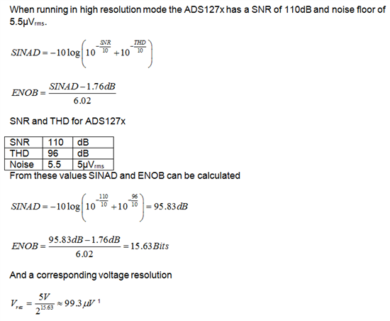
In high resolution mode the ADS1274 has ENOB of 15.63 which results in a resolution of approximately 100uV.

My question:
Since the resolution of the sensor is 660uV and the resolution of the ADC is 100uV, do you still recomend that I amplify the signal in order to fill the full range of the ADC? (right now I am only using about 50% of the full range).

I suspect that I am doing to many assumptions and that I am missing some fundamental theory regarding these ADC range considerations? Any help is welcome.

  • I continued the number crunching and found that with ENOB=15.63 there are approximately 50710 (noise free) counts available.

    If the resolution of my accelerometer (@100 Hz bandwidth) is 1 mg and the full scale range is 4g than this requires 4000 counts.

    The full scale voltage swing of the accelerometer occupies approximately 26000 counts in the ADC but i only need 4000. As long as the output voltage of the accelerometer is safely within the limits of the ADC input (which it is), than there is no need for any signal conditioning/amplification (I am assuming).

    Except maybe a buffer to drive the ADC input but that I have under control.

  • Hi Bogi,

    I don't have an answer for your question, but I would be interested in knowing what accelerometer you are using.  I've been looking for an analog output unit for a project I anm working on and all I've found so far are digital output (I2C type) devices.

  • Hi Bogi,

    The need for a buffer will depend on the output impedance of the sensor.  If the sensor output impedance is higher (relatively to the ADC input impedance) then you will create a voltage divider.  This will affect the accuracy of the measurement.  If you only are looking at relative values this may be ok (one axis relative to another), but you will not have accuracy.

    Best regards,

    Bob B

  • Hello Bob Benjamin

    Thank you for your reply. However, my question is not regarding buffering of the signal. This I will have to do no matter what.

    My question is regarding Amplification of the signal; I am in doubt what I will gain from conditioning the signal by amplifying it to fit the full input range of the ADC. This will require both amplification and shifting of the 0-level voltage. I wanted to avoid this by choosing a higher resolution ADC.

    Thanks
    Bogi Magnussen

  • Hi Bogi,

    I'm sorry that I missed the point of your question.  In a lot of cases we have questions related to the need for a buffer, so I apologize that I neglected to read your question thoroughly.

    It is not clear to me how you made your calculations regarding the ADS1274.  Based on the maximum specification table the maximum noise of the converter at high resolution will be 12uV rms with shorted inputs.  This gives me an ENOB rms of about 18.6 bits for a 2.5V reference.  Noise free bits will be about 17.1 bits.

    The noise free counts will be relative to the number of noise free bits times the ratio of the sensor output range to the full scale range.  If the sensor out is +/-2g with 0.66V per g, then I calculate the noise free counts as 37086.  This appears to achieve your goals, however this is making some assumptions.  You mentioned earlier the noise of your sensor, but there are other sources of noise as well.  These include power supply noise, reference noise, and poor PCB layout that can also pick up noise.  The answer to your question is not really that easy to answer.

    If you feel you are close to your goals, there is one other method to increase dynamic range without amplification.  That is by lowering the reference voltage.

    Best regards,

    Bob B

  • Hi Bob

    Thank you for a very thorough answer. I have attached my ENOB calculations.

    I understand off course that there are other sources of noise as well and that these will change my noise calculations somewhat. How do you calculate ENOB? Is there a TI application note i can read? It would be nice to reference my own calculations to a TI application note, as i often find these very good.

    Anyway: Assuming I have 1mg resolution with +/-2g FS with 0.66 V/g i need 4000 noise free counts. Ideally the ADS1274 can give me 37086 counts in this range so there is no need for signal amplification? Even with all the other noise sources and non-ideal components i am still quite far away from the noise floor of the Accelerometer.

    Put in another way. Theoretically the ADC with 17 noise free bits has a resolution of 5V/(2^17)=38uV corresponding to 38uV/(0.6 V/g)=57ug (using the current accelerometer). As long as the resolution of the accelerometer is much lower than 57ug, amplification is not required.

  • Hi Bogi,

    There are a couple of ways of looking at ENOB.  With the ADS127x family it can be done in equally valid ways depending on the point of view, and both results will be different.  One is an AC perspective (SINAD derived case) and the other a DC perspective (which some call effective resolution.)  Looking at the DC case ENOB (or effective resolution) is ln(Full-ScaleRange/RMS noise)/ln(2).  For RMS noise I used the worse case maximum in the datasheet and not the typical.  It happens to be that the AC perspective is the overall worse case, so that may be the better way to view, even though I would assume that your sensor output is essentially DC (but of course my assumption may be wrong.)

    As you have shown by your calculations, you should not need any amplification (which may add some additional noise anyway.)

    Best regards,

    Bob B

  • Hi Bob

    Thank you very much for your attention. Interfacing ADC's is an exciting subject with many pitfalls. The non-ideal characteristics of sensors, ADC's and conditioning circuits have a much larger influence than most people think.

    I will measure the rms noise of the ADC by shorting the inputs. The datasheet values are most likely much worse than what I am getting. At the moment I am clocking the ADC directly from the AM3359 processor with a resulting sampling rate of only 256 Hz in high resolution mode, so I expect my noise figures to be significantly better than what is specified in the datasheet.

    Regards
    Bogi Magnussen