This thread has been locked.

If you have a related question, please click the "Ask a related question" button in the top right corner. The newly created question will be automatically linked to this question.

TLC5540

Other Parts Discussed in Thread: TLC5540, TXB0108

From the datasheet of the TLC5540.
I have some questions i can not sure.
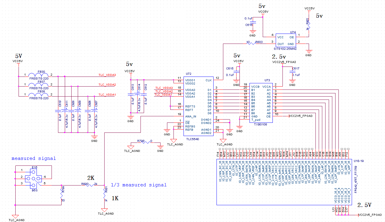
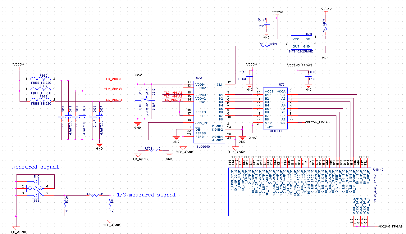
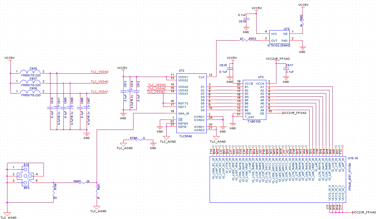
1.If i want the chip of TLC5540 can operate with Vreft - Vrefb = 5 V ,i connect the pins "REFBS" and "REFB" to the GND, and connect the pins "REFTS" and "REFT" to the +5V. Is it right ?
2.Can the measured analog signal be durectly connected the analog input port (pin19) ? 
3.What is the input clock's level ? Is it 5v ?
4.What is the outputs' (D1--D8) level ? Is it 5v ? If i want to connect the output of TLC5540 to the virtex6 FPGA , but the maximum voltage virtex6 FPGA can accept  is 2.5v , i use a level converter (5v to 2.5v) ,for example TXB0108 . Is it ok ?

5.What is the vaule of the input impedance of the chip ? Because I want to  divide the measured signal ,then connect the dividen siganl to the analog input port (pin19),I need to know the value of the input impedance of the chip!
Followed is the schematic :

Is the design right ?

  • Hi Lei,

    1. Yes, that reference setup is correct for a 5V reference.

    2. Yes, the signal should be connected to the analog input. Make sure that the voltage level stays within the reference voltage range and does not exceed the absolute max for the input pin. For your 5V reference, the signal should be centered at 2.5 V and swing a maximum of +/- 2.5 V.

    3. The clock should swing from 0 to 5 V. If the clock driver is far away from the TLC5540, you may need to properly terminate the transmission line to avoid overshoot and avoid violating the absolute maximum voltage levels.

    4. The outputs will also be 5V. Using a level translator is fine. It is best to use a single 9-bit (or larger) translator for the 8 bits and the clock to minimize skew between data bits and clock.

    5. I expect the input impedance to be sufficiently high since the ANALOG IN pin drives the sample and hold circuit directly. Regarding your divider, can you tell me your expected analog input voltage range?

    Regards,
    Matt Guibord 

  • Hi Matt,

    Thanks for you reply !

    1.You said "It is best to use a single 9-bit (or larger) translator for the 8 bits and the clock to minimize skew between data bits and clock." That is in order to  ensure datas and clock synchronization , is it right ?

    2.I expected analog input voltage range is 0-5V.  How much value of  the input impedance  is appropriate for the chip ?

  • Hi Lei,

    1. Yes, that is correct. The speed is slow enough that there is quite a bit of timing margin, so it may not be too critical.

    2. Yes, the input voltage is 0-5 V in your configuration. I would expect the input impedance at DC to be greater than 10 kOhm.

    Regards,
    Matt Guibord