This thread has been locked.

If you have a related question, please click the "Ask a related question" button in the top right corner. The newly created question will be automatically linked to this question.

ADS1281 - Excessive noise with 1.000MHz clock

Other Parts Discussed in Thread: ADS1281

Hello.

I'm encountering issues using ADS1281 converter.

I want to read the converter with a data rate slower than 250sps.

I'm in register mode and continuous mode.

These are my register configurations :

REG00 = 20

REG01 = 42

REG02 = 08

REG03 = 32

REG04 = 03

REG05 = 00

REG06 = 00

REG07 = 00

REG08 = 00

REG09 = 00

REG0A = 40

The inputs of the converter are shorted together and put to ground.

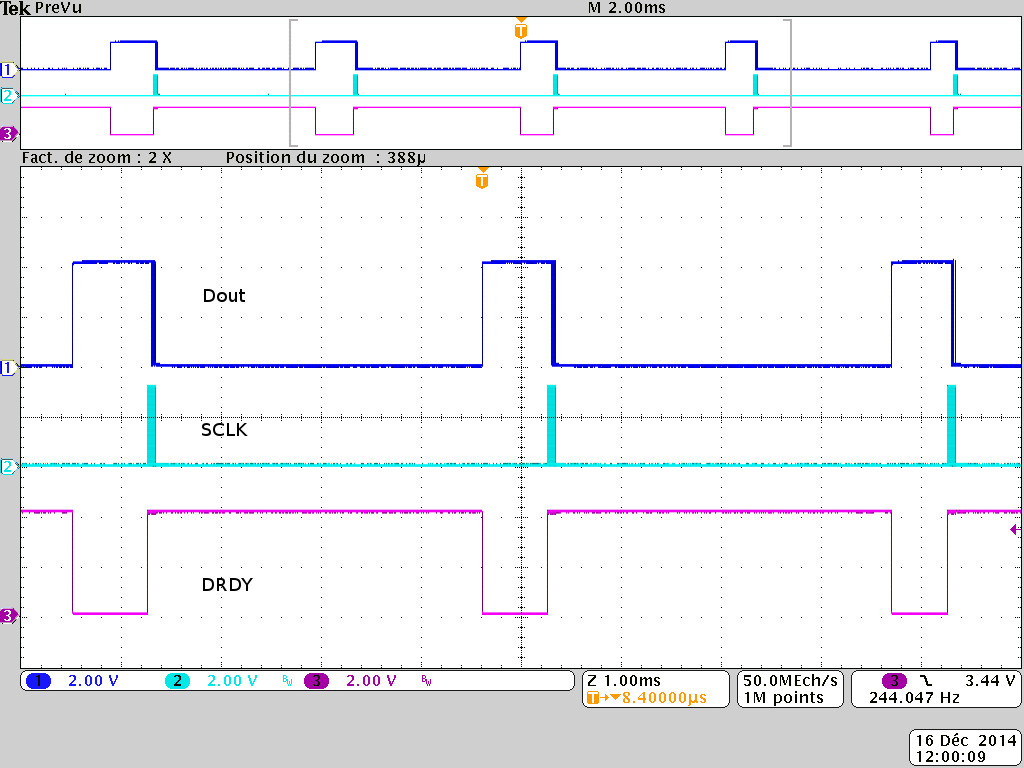
When I read at 61Hz (with a 1.000 MHz CLK), the noise is higher than 244Hz (4.000MHz).

Left part : data (in V) with a 4.000 MHz clock

Right part : data (in V) with a 1.000 MHz clock

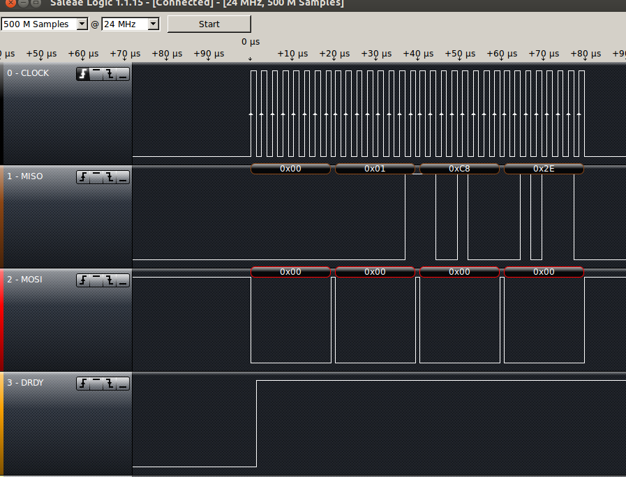
And the SPI communication seems good :

(SCLK = 400Khz)

Is there something wrong here ? I don't understand where is my mistake.

May it come from schematic ?

Thank you,

Romain.

  • Hi Romain,

    Welcome to the TI E2E forums!

    The error may be occurring when you switch the CLK speed from 4.096 MHz to 1 MHz.
    You could have some glitches which are causing you to get out of sync with the ADS1281.

    I see that your conversion measurement switched from a negative result to a positive result and that the noise is very non-Gaussian!
    I'd expect the offset to change slightly, but it appears like something else is happening here.

    I would recommend toggling /RESET to reset the SPI interface (after switching the clock frequency) .
    Then reconfigure the device and restart the conversions to see if the "noise" goes away.

    Best Regards,
    Chris

  • Hello Christopher,


    I forgot to mention that I have the same results when the converter is powered on with 1MHz.
    (On my last results, I just switch the clock on the fly to see the difference between 2 results in one graph).


    I tried anyway to reset with RESET pin or command, but nothing change.

    I was wondering if it can come from supply or reference voltages?  (but I don't understand why it works fine with 4MHz.)


    I just check with an oscilloscope my serial signal quality, and it looks ok.

    But I notice a little difference :

    With 4MHz :


    With 1MHz:

    With 4MHz clock, the Dout pin goes high when DRDY goes low. Do we care about this ? Or is it a problem ?
    (Or is it just because the data is negative and start with 0xFF ? )

    Thank you for your answers !

    Romain.

    EDIT:

    I just saw that my supply was a bit too high on the lasts results.

    I fixed it (and i hope the converter has not been damaged, but it still works properly at 4MHz).

    Now, with my 1MHz clock, this is what I read :

    (The units are volts and seconds).

  • I just found the cause of this problem.

    The positive reference voltage is unstable when I slow the clock.
    I don't know why, but I will see with the designer of my electronic board.

    I should have checked that before asking this question...

    Thank you for the answer!

    Best Regards,

    Romain.
  • Hi Romain,

    Good find!


    To answer your previous question:

    • The MSB of the data appears on DOUT when /DRDY goes low.

    Best Regards,
    Chris