A related question is a question created from another question. When the related question is created, it will be automatically linked to the original question.
If you have a related question, please click the "Ask a related question" button in the top right corner. The newly created question will be automatically linked to this question.
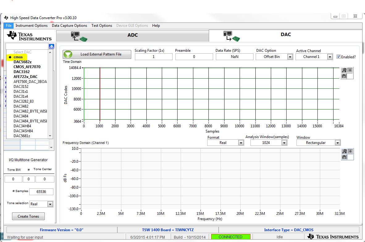
TSW1400EVM will work with the DAC5688/89 EVMs. You have to select cmos from the device list as shown in the picture below to load the firmware.
Here is the updated section 6: DAC5668/88/89EVM initial Power Up and test.
DAC5668/88/89EVM Initial Power Up and Test
The steps described in this section show how to connect and configure the DAC5668/88/89EVM for evaluation under the default settings.
Connect the DAC5668/88/89EVM digital connector (J2 and J7) to a digital test pattern generator capable of providing 3.3-V or 1.8-V CMOS logic level inputs such as Texas Instruments TSW1400EVM.
Use the DAC5668/88/89 EVM DAC_CLKOUT (J21) SMA connector to trigger the pattern generator. In the case of the TSW1400EVM pattern generator, the trigger input is CMOS CLK (J7) SMA connector.
Connect the 1.8-V (J13/J14), 3.3-V (J15/J16) and 5-V (J10/J11) power supplies. Ensure that each supply is not drawing more than 1 A of current. Turn on the power supplies. Press SW1 to reset the board.
Provide a single-ended, 1-Vrms, 0-V, offset sine-wave signal to the DAC5668/88/89 EXT_VCXO (J20) SMA connector. LED D3 should illuminate indicating that a signal has been detected. If not, verify that the correct signal is being provided.
Connect a 0-dBm LO signal to the RF_LO_IN (J23) SMA connector.
Connect one end of the supplied USB cable to an available USB port on the host PC. Connect the other end of the cable to J1 on the DAC5668/88/89EVM.
Open the EVM Software. The DAC software detects if the USB port is active and if it is capable of reading the EVM serial number. Read the Status Messages to determine if the communication is successful.
Program the CDCM7005 and DAC registers as necessary. An example configuration file example.txt is included under the installation folder: C:\Program Files\Texas Instruments\DAC5688/89\DAC5688/89Configuration Files\
Program and run the pattern generator. If using the TSW1400EVM, see the user’s guide for more information on how to set up a digital pattern.
The DAC5668/88/89EVM RF output can be monitored using SMA connector J6 (RFOUT).
You should be able to use the user guide for the DAC5688 EVM for rest of the configurations. Below is the link for the user guide.