This thread has been locked.

If you have a related question, please click the "Ask a related question" button in the top right corner. The newly created question will be automatically linked to this question.

PROBLEM IN DAC7716 IC

Other Parts Discussed in Thread: DAC7716

Dear Sir,

I am not getting analog volgate variation at Vout-0,1,2,3 pin. always getting 0V. Please tell me the reason .Iam sharing my code tell me were is the problem,My ref voltage is +5V. IAm sharing my code kindly let me known where is the problem.


void write_dac_3byte(long add) 
{
unsigned char i;
long temp;
// DelayMs(4);
for(i=24;i >=1;i--)
{
SPI_SCL=1;
temp=add;
temp =temp >> (i-1);
temp= temp & 0x01;
// send_hex(temp);
if(temp == 0x01)
{
SPI_SDO =1;
}
else
{
SPI_SDO =0;
}

SPI_SCL=0;
DelayMs(4);

}
}


/

//-------------------DAC WRITING -----------------------------------//
void DAC_write (void)
{
DAC_LATCH=0; // data are sending
MUX_SEL(5); //CS=0;
write_dac_3byte(0x00000000); // command register write were on byte 3 address is 0
write_dac_3byte(0x00012000); // monitor register write were on byte 3 address is 1 to select dac-1 = 2
write_dac_3byte(0x00057ff0); // dac input output register write were on byte 3 address is 5 to select dac-1= 00 GIVE dac DATA INPUT
write_dac_3byte(0x000900FF); // zero register write were on byte 3 address is 9 to addjust offset error +1.9922lsb
write_dac_3byte(0x000D007F); // gain register write were on byte 3 address is D to adjust gain error +7.9375lsb
PORTA=0xFF; // CS=1
DelayMs(10);
}
///////////////////////////////////MAIN FUNCTIO N ///////////////////////////
void main(void)
{
long DOR_BUFFER,FULL_BUFFER,OFF_BUFFER;
TRISA=0b00000000; // mux selection A,B,C output=0,STARt CONV,HYDRO_TEST;AC_MAG_GAIN=;
TRISB=0b11110000; // CHANNEL SELECTION A0-A3=0;ADC16_BUSY,X,Y,ZADC_DRDY=1
TRISC=0b11010000; // spi SDO,clk output=0,SDI input=1;TX=1;RX=1
ADCON1=0x86;
while(1)
{
DAC_write();
}
}

  • Howdy Arti,

    For verification purposes, can you provide a scope capture of a write transaction? This will let me know if timing specifications are met for proper communication. For reference, most of these specifications are provided in page 9 of the DS.

    Additionally, is it possible to provide a schematic?

    Best Regards,
    Matt

  • Dear Sir,

    Kindly find the Schematicts and waveform.

    DAC7716 Wave form and Schematic Diagram

    Fig 1. SDI


    Fig2.SDO


    Schematic DAC7716


    Fig3 Interfacing with PIC16F876A IC DAC7716waveform .docx

  • Howdy arti,


    Thanks for the information.  In order to verify timing specifications I will need a complete capture of the following signals during a complete SPI transaction.

    • SCLK
    • SDI
    • /CS

    A separate oscilloscope capture of /LDAC included with the above signals will also be helpful for debug.

    From a connection standpoint, I don't see anything out of the ordinary in your schematic.  However, all AVSS/AVDD pins should include bypass capacitors, as included on other supply pins.  I would also suggest adding an additional 1-10uF on the larger supplies.

    Best Regards,

    Matt

  • Hi Matt,

    Kindly find all waveform.and one more thing i want to ask,in Schematic I have connected RST pin to 5V,Vmon is open ,Ain is open ,GPIO0 and GPIO is open becuse iam not using these pins,and LATCH defined as output of controller and input of DAC7716. Please verify and let me known i did correct.DAC7716 waveforms(24.9.15).docx

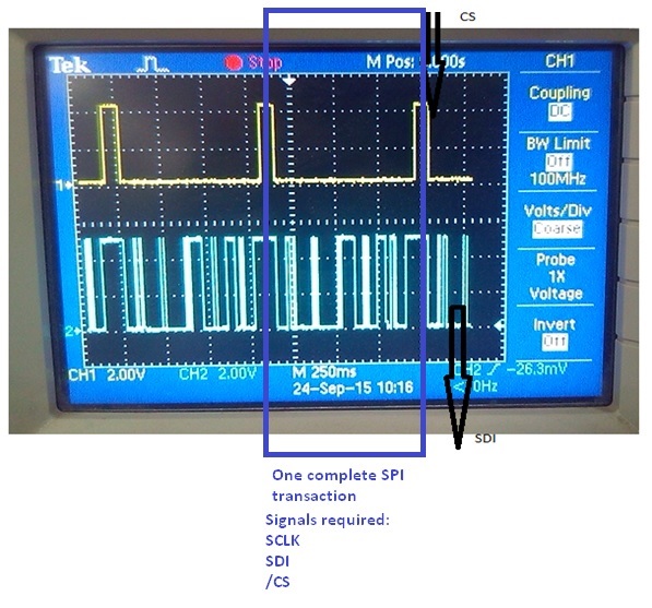
  • You need to zoom into one transaction as well as provide me with the write details of the transaction.  For reference I've included the below images.  One complete transaction is described as one SPI register write which follows the following illustration.  Note how the CS signal asserts low for one transaction.  I've highlighted what you would need to zoom-in in the image you've provided.  Please also list the 24 bit value you are trying to write to the device for the captured SPI write. 

    Can you also include all 3 signals in one scope capture (SDI/SCLK/CS)?  If you only have a 2 channel oscilloscope then (SCLK/SDI) will do but verify that the transaction only lasts for one active low /CS.

  • The /RST/GPIO/Vmon pin connections are fine. However, usually the active low inputs are tied to a pull-up resistor to IOVDD. If you plan to use GPIOs in the future it may be good to note that most have open drain outputs, therefore a majority of the times you will need a pull-up to IOVDD as well.
  • Dear Matt,

    Kindly find my code how iam sending 24 clock with the address and me me my code is write or not.I have doudt on command registor where iam making PD-A and PD-B =0 in Command registor, Is should be 0 or 1. and LD= 1,RST =1. code doen for DAC-1


    DAC7716 Code in embedded C interface with PIC16F876


    void write_dac_3byte(long add)         //sen 3 byte serial   checked OK

         {

                                    unsigned char i;

                                    long temp;

                                    for(i=24;i >=1;i--)

                                   {                             

                                           SPI_SCL=1;

                                           temp=add;

                                           temp =temp >> (i-1);

                                           temp= temp & 0x01;

                                           if(temp == 0x01)

                                                    {

                                                     SPI_SDO =1;

                                                    }

                                           else

                                                    {

                                                         SPI_SDO =0;

                                                    }


                                                    SPI_SCL=0;

                                                    DelayMs(4);    


                                    }             

                    }

    //-------------------DAC WRITING----------------------------------------//

    void DAC_write (void)

    {

                    DAC_LATCH=1;   // data are sending

                    MUX_SEL(5);    //CS=0;

    write_dac_3byte(0x00006300); // command register write were on byte 3 address is 0 LD=1,RST=1

    write_dac_3byte(0x00012000); // monitor register write were on byte 3 address is 1 to select dac-1 =

    write_dac_3byte(0x00057ff0); // dac input output register write were on byte 3 address is 5 to select dac-1= 00 GIVE dac DATA INPUT

    write_dac_3byte(0x000900FF); // zero register write were on byte 3 address is 9 to addjust offset error +1.9922lsb

    write_dac_3byte(0x000D007F); // gain register write were on byte 3 address is D to adjust gain error +7.9375lsb

                    PORTA=0xFF;       // CS=1

                    DAC_LATCH=0;    // data are updating

                    DelayMs(50);                    

    }

    ///////////////////////////////////MAIN FUNCTIO N ///////////////////////////


    void main(void)

    {

                   long DOR_BUFFER,FULL_BUFFER,OFF_BUFFER;

                    TRISA=0b00000000;  

                   TRISB=0b11110000;     // CHANNEL SELECTION A0-A3=0;ADC16_BUSY,X,Y,ZADC_DRDY=1

                    TRISC=0b11010000;     // spi SDO,clk output=0,SDI input=1;TX=1;RX=1

                    ADCON1=0x86;  

                   while(1)

                    {

                                    DAC_write();

                    }             

    }
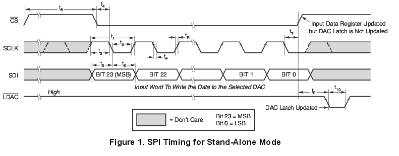
  • Please provide the following information, through it I will be able to verify timing specifications as well as ensure the SPI clock polarity is set correctly.

    Thanks,

    Matt

    "Include all 3 signals in one scope capture (SDI/SCLK/CS).  If you only have a 2 channel oscilloscope then (SCLK/SDI) will do but verify that the transaction only lasts for one active low /CS."

  • Hi Matt,

    Thanks for your support.I got output.Now my DAC7716 is working fine

  • Howdy arti,

    I'm glad to here that. May I ask what the fix was?

    Best Regards,

    Matt

  • hi Matt,

    problrm was not in hardware.I did changes in Command Regitster and some changes in code for latch and CS.