I have a strain gauge product I am designing that uses an MCU and the ADS1220 for bridge circuit analysis. I have previously prototyped the application on a breadboard and wrote a complete program along with a ADS1220 header file for SPI communication with the ADS1220. Currently on my breadboard everything is working quite well and proven out; I can talk with the ADS1220 with no problems and continuous conversions.
My issue is this; I have moved on from the breadboard prototype onto the PCB prototype. Upon soldering the MCU, LCD, and ADS1220 onto the PCB (for initial error checking), I uploaded my programs onto the MCU and found that I could not receive constant communication from the ADS1220. I have been pondering this issue for a couple days now and have tried quite a few troubleshooting methods. I initially had two individual analog power regulators (REF3233) for the the reference and analog power pins on the ADS1220. I was seeing large voltage drops on these pins, the ADC reference pin went from 3.3V down to 0.75V and the AVDD pin went from 3.3V down to 1.5V, when I would randomly receive a single conversion from the ADS1220 then all conversions would cease. I suspect that the reference input pin is current buffered and absolutely should not have been drawing more that 10mA (ref3233 max current) to cause such a voltage drop (the ADS1220 ref pin is rated at 10nA). Therefore, I decided to de-solder and replace the ADS1220 with a new one and also removed the analog regulators. Note: At any given time before or after the analog voltage drops, the DVDD pin remained at a steady 3.27V from the MCU regulator. With this in mind, I decided to tie the ADS1220 AVDD pin to the DVDD pin and am currently, seeing a good constant voltage with no drops. Note: I am not using the REF3233 regulators at this time for troubleshooting isolation. I then powered the circuit with MCU, and am still seeing no communication from the ADS1220. I had previously powered the analog and digital power pins on the ADS1220 from a single regulator with no communication problems on the breadboard circuit.
What my PCB circuit currently looks like is brutally simple at this point, I only have the MCU tied to an LCD for communication verification via I2C and the MCU tied to the ADS1220 via SPI. All SPI traces are routed directly to their respective pins from the MCU to ADC, and I have completed continuity checks on every trace. A current concern of mine is that, on the breadboard all wires and pins have an intrinsic resistance on them, and on the PCB everything is soldered therefore significantly less resistance between MCU and ADC on every SPI connection. I had noticed that the ADS1220 recommended putting 47ohm resistors in series with SPI traces to "soften" sharp transitional spikes. The breadboard SPI connection resistance is currently in mOhm not Ohms, and PCB is in uOhms.
Other tricks I have tried are: Slowing the SPI communication speed down to dampen transistional spikes, Increased startup time before initializing the ADS1220 giving time for the power pins to stablize, and adding the AVDD and DVDD decoupling capacitors to my PCB circuit.
Other than that I am practically exhausted of all my troubleshooting magic tricks and have come to a crossroads. Any help or insight you have on this issue is greatly appreciated!
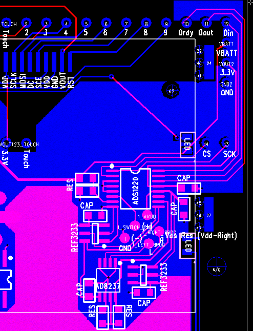
Attached below is snapshot of the portion of my circuit I am currently working with.