


Hello,
We are using TSW1400EVM and AFE5851EVM to implement some system.
And to let the AFE input signal and output signal be more accurate, we want to know more about AFE5851EVM.
As we know, AFE5851EVM have anti-alias low-pass filter, high-pass filter, variable gain amplifier, ADC...etc.
Like this picture. If you have time, can you explain more about this ?
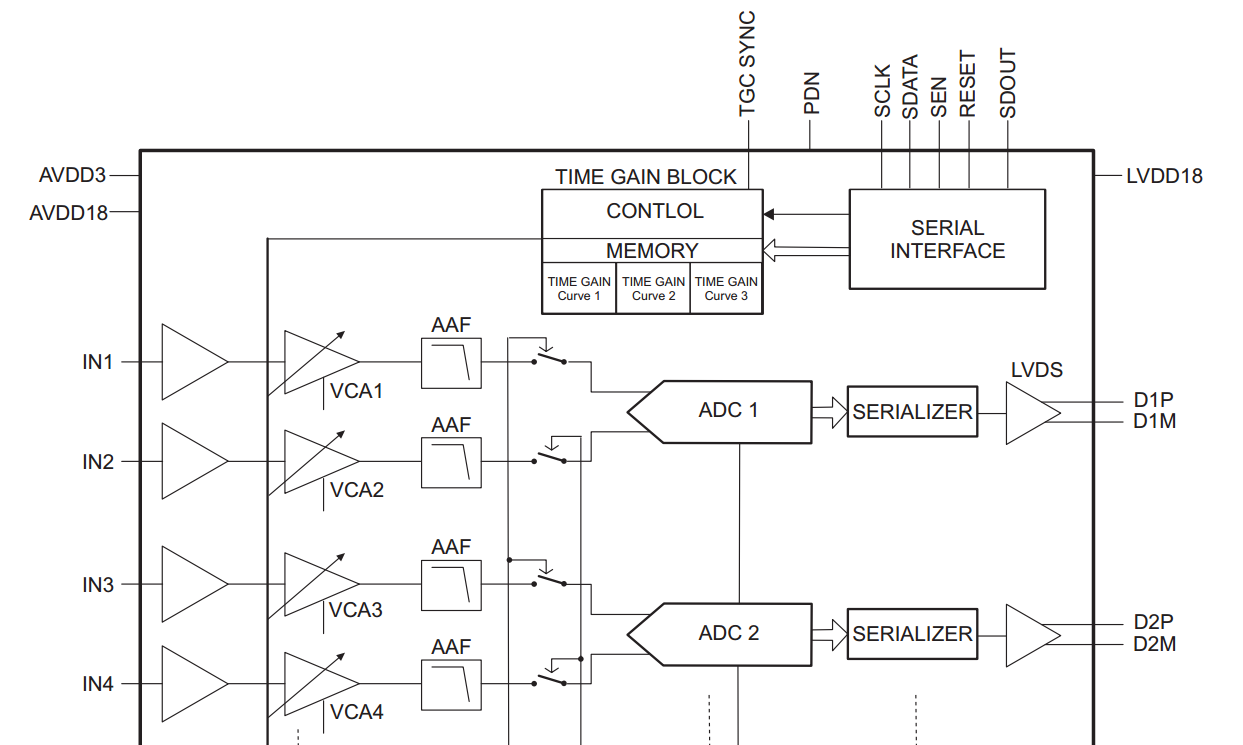
Or as we know, the data is simply transport as below way.
Analog input => VGA => ADC
The analog input is limited 1Vpp, and ADC input is limited 2Vpp.
So I try two different signal input the AFE5851EVM, (-1Volt~0Volt sine wave, and 0Volt~+1Volt sine wave)
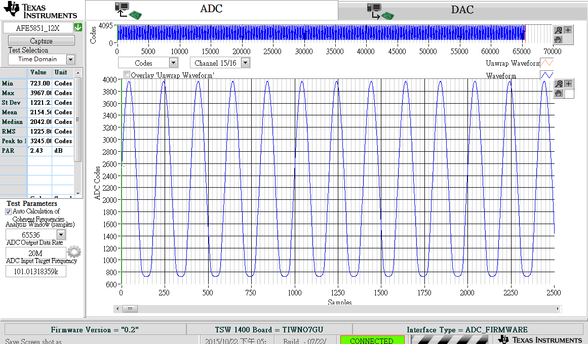
And I get same waveform in HSDC Pro.
Is it means the analog input data have been removed DC(offset)?(Which place to removed the DC)
After I try more tests for capturing in the HSDC Pro, all waveform are average in 204X point.
So I have two more questions.
Is 0~4095(12bits 00...00 ~ 11...11) point in HSDC Pro means the 2Vpp?
And all capture data would average to the middle point?
And I do one more test for analog input.
As we over the 1Vpp limit, the waveform we captured is like below.(input 1.8Vpp sine wave,0dB)
The waveform isn't over the 2Vpp, but is different to others.
Why the waveform (over 1Vpp) would be like below picture?
p.s. Because our data would in 100kHz. So all above i mentioned test is in DC coupling mode.
My email
JhinCiHong19901008HY@gmail.com
Kind regards,
Jerry
