This thread has been locked.

If you have a related question, please click the "Ask a related question" button in the top right corner. The newly created question will be automatically linked to this question.

How to use ADS4222EVM

Other Parts Discussed in Thread: ADS4222EVM, TSW2110EVM

Hello,

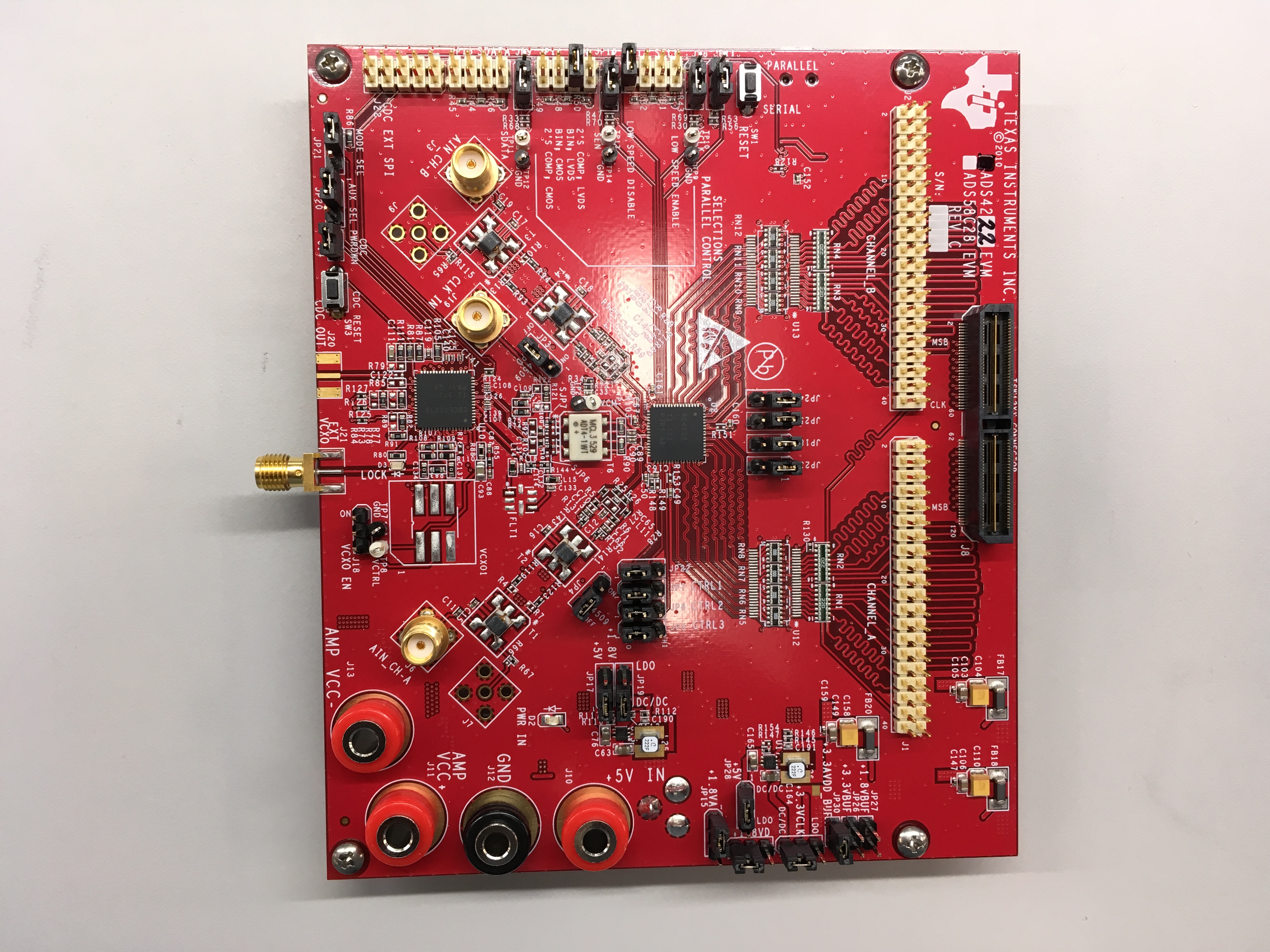
I've purchased ADS4222EVM (REV C) and I'm trying to use it (CMOS, I've removed the necessary resistors and plugged in U12 and U13).

When I connected it to my PC the GUI software didn't recognize it. So I used the solution from here and then the green light was indeed bright.

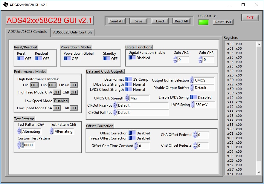
I've tried setting a test pattern to alternate and connect logic analyzer to either J1 and J2, but I didn't capture anything. I've also tried to connect a clock source to CLK IN using the TSW2110EVM. Again, with no success.

I'm not really sure that the USB is really transmitting data or that I just fooled the GUI (as there is no real indication whether it is working or not).

What am I doing wrong?

Thanks,
Or Dagmi.

  • Or Dagmi,

    Verify the jumpers on your EVM are per the attached figure. Are you using GUI v2.1? Did you try using a clock source from a signal generator? I ran this setup using a 100MHz clock from a signal generator with no problems. Do you have a TSW1400EVM to capture the results? I will try using a TSW2110EVM as a clock source.

    Regards,

    Jim


  • Hey Jim! Thanks for your reply.

    I think that this jumper configuration is for LVDS, isn't it? I want to use the CMOS.
    And yes, I'm using GUI v2.1.
    I don't have TWS1400 (yet.... I've ordered it but it's still on the way). I've tried to use Saleae logic analyzer to capture the output from J1 and J2.

  • Or Dagmi,

    The board is setup for serial mode so the LVDS jumper is ignored. When I set the Output Buffer Selection to "CMOS" in the GUI, the output of the ADC changes from LVDS to 1.8V CMOS. When I used the TSW2110 as an input clock, I was able to capture CMOS data just fine. One way to verify if the GUI is working properly on your setup is to power up the EVM with a lab power supply that allows you to monitor current. With the board running, using the GUI, select "OFF" for Powerdown Global and you should notice the current will be reduced. 

    Regards,

    Jim

  • Hey Jim,

    I do see a difference of 0.01 Amper between the two configurations of "Powerdown Global".

    I've connected CLK IN to TSW4806 (to J15  - 62.5 MHZ clock), and I've tried you jumper configuration. Still, when I connect the logic analyzer to J1 /J2 I cannot see a thing (when running test pattern).

    This is my board:

    and this is the configuration I've tried:

    Thanks,
    Or.

  • Or,

    You have two jumpers in the wrong location. Move the shunt on JP12 to pins 1-2 and the shunt on JP14 to pins 5-6 (see the photo I sent earlier). With a 65MHz clock, the board should draw 0.068A. After power down this should be 0.033A.

    Regards,

    Jim

  • Jim,

    The shunt on JP12 is on the pins 1-2. And JP14 was there and on 3-4 for testing (as it says that this is the BIN, CMOS). Neither worked.

    I've got two boards at hand. One with U12 and U13 connected and another one with R5 to R12 connected.

    The one with U12, U13, draws 0.5 amper. while the one with R5 to R12 draws around the amount you mentioned. Maybe I've damaged it while putting U12 and U13 on?

    Or.

  • Or,

    Did you remove RN5-RN12 before installing U12 and U13? Do you see CMOS level signals at the input of U12 and U13 using a scope probe? Did you verify the clock output at the ADC, then the at the input of the U12 pin 26? Is R130 installed? Are shunts on pins 1-2 of JP23, JP18, JP25 and JP24? Are you measuring 3.3V on pins 7 and 18 of U12 and U13 and 1.8V on pins 31 and 42? There may be a short on one of these supplies if the parts were not installed properly. If all of this looks fine, you can ship me the board and we can either repair it or replace it for you.

    Regards,

    Jim 

  • Jim,

    Of course RN5-RN12 were removed prior to the installation of U12 and U13.
    I don't really see signal in U12/U13. I do see something in pin 44, 0.6V. but other than that nothing.
    R130 is there. And the JP28, JP18, JP24 and JP24 are shunted on pins 1-2.

    I would be more than happy to ship you the board, where to?

    Thanks,
    Or.
  • Or,

    Ship it to the following Address:

    Jim Seton

    Texas Instruments

    12500 TI Blvd

    M/S E3000

    Dallas, TX 75243

    (214) 567-7283

  • Thanks!
    I will send it now using fedex. BTW, I'm located in Israel, it won't be a problem for sending it back, right?
  • Or,

    It will not be a problem. Please send me your address and a phone number, I will modify my board for CMOS output, and send it to you.

    Regards,

    Jim

  • Hey Jim,
    Thanks!
    I've sent you my board using FedEx (do you need the tracking number?)

    My address is:
    Argus Cyber Security
    24 Raoul Wallenberg st.
    Enterance C, Floor 10.
    Tel Aviv, 6971920, Israel
  • Hello Jim,

    My name is Tali and I'm handling the purchase and business operations at Argus Cyber Security Ltd.

    The item in discussion was purchased via Mouser Electronics.

    Should we involve them in the return process?

    Also I have a few other questions regarding the process:

    1. How do we send it back without bearing costs? Can you provide the proper documentation and your Fedex #? (We tried to send it directly but was requested to issue a proforma invoice).

    2. How do we receive a new working replacement for the ADS4222EVM?

    Please see attached the invoice from Mouser for this item (line #1).

    Thank you,

    Tali Peled

    Business Operations Manager

    tali.peled@argus-sec.com

    +972-54-4404642

    41050792.pdf

  • I am looking into this.

    Jim
  • Or,

    We finally got your board modified for CMOS interface and tested. It shipped out yesterday. Tracking info below.

    Regards,

    Jim

    Your Shipment information:
    Transport Order number: NA
    Delivery Note: 762006986
    Shipment number: 409383262
    Invoice number: 5402129407
    Carrier Tracking Number (AWB): 5102893003
    Freight Forwarder: DHL Express
    Ship To TI Plant Code:

    Tracking info will be available after 6pm.

    To track the shipment:

    1. Go to DHL
    2. Select your country and click "GO"
    3. Enter the Carrier AWB,5102893003, in the "Track It" field.
    4. Click on "Track".