


Other Parts Discussed in Thread: ADS8860
I'm using an ADS8860EVM-PDK, but I've detached the board containing the ADC itself and connected it to a C2000 device. I'm running the CONVST signal with a PWM (1us on, 100kHz freq), and running a 20MHz SPI clock. It is powered by a 5V supply and I've connected all essential signals according to the ADS8860EVM-PDK User's Guide (SBAU213).
I'm using a function generator to provide a DC signal and am attempting to map the DC voltages to the values read by the C2000 out of the ADC. JP4 jumper is open, which should be 0-4.5V on the input of the circuit means 0-4.5V on the input to the ADC (inverted).
When I sweep across the range, I get this:
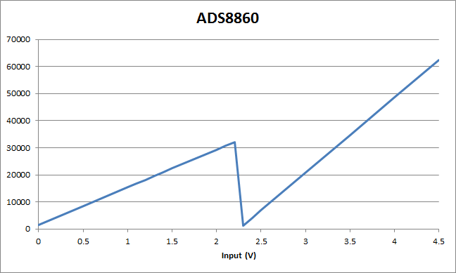
The fact that it restarts at exactly half the range (as well as the slope difference being 2) indicates it's something simple like I'm just interpreting the bits wrong, but can't figure out how according to either of the documents (EVM User Guide or the ADC data sheet).
Should the 16 bits be signed or unsigned?
Are there any shifts or scaling necessary out of the raw SPI buffer?
Is it possible I'm reading the bits out in the wrong order?
Thanks!


