This thread has been locked.

If you have a related question, please click the "Ask a related question" button in the top right corner. The newly created question will be automatically linked to this question.

ADS1243 DRDY notification

Other Parts Discussed in Thread: ADS1243, ADS1240, ADS124S06

Good day.

I am having some problems with regards to waiting for the DRDY pin to go low. I am exciting the strain gauges, setting the mux and differential channels. I then send the RDATAC command, delay 100ms, then initiate sclk to read the data in a loop 8 times then average off. I am noticing in some instances, units are left waiting indefinitely for the DRDY pin to drop, this obviously without any timeout waiting for the pin to drop. This is a new find as some units have been operating successfully for over a year. Question is, if i "miss" the DRDY pin dropping low, or if the pin does not drop low at all, can i merely resend the RDATAC command, or should i send the RESET command and start from the beginning. Code is below. Any input would be appreciated.


void set_A2D_channel(unsigned char chan)
{
  AD_CS=0;         // Select A/D
      switch(chan)
      {
        case 0:   WriteSPI1(0x51);      // Write to Register Starting at 1 (MUX)
                    DelayUs(20);
                  WriteSPI1(0x00);      // Ending at Register 1 (MUX)
                    DelayUs(20);
                  WriteSPI1(0x04);      // Channel 0 inputs: differential Ch 4
                    DelayUs(20);
                  break;
        case 1:
                  WriteSPI1(0x51);      // Write to Register Starting at 1 (MUX)
                    DelayUs(20);
                  WriteSPI1(0x00);      // Ending at Register 1 (MUX)
                    DelayUs(20);
                  WriteSPI1(0x15);      // Channel 1: differential Ch 5 - test: swap rails
                    DelayUs(20);
                  break;
           case 2:
                  WriteSPI1(0x51);      // Write to Register Starting at 1 (MUX)
                    DelayUs(20);
                    WriteSPI1(0x00);      // Ending at Register 1 (MUX)
                    DelayUs(20);
                    WriteSPI1(0x26);      // Channel 2 inputs: differential Ch 6
                    DelayUs(20);
                    break;
        case 3: 
                  WriteSPI1(0x51);      // Write to Register Starting at 1 (MUX)
                    DelayUs(20);
                  WriteSPI1(0x00);      // Ending at Register 1 (MUX)
                    DelayUs(20);
                    WriteSPI1(0x37);      // Channel 3 inputs: differential 7 - test : swap rails
                    DelayUs(20);
                  break;
      }
}

void get_A2D_value(void)
{
  unsigned char i,j,flush_read = 0;
 
    ad_value[ad_channel] = 0;
    WriteSPI1(RDATAC);                      // Start reading continuously
    DelayMs(100);
    for(j=0;j<9;j++) {
        if(j==0) {flush_read = 1;}
        else {flush_read = 0; }
        while(AD_DRDY);
        for(i=0;i<3;i++) {
            ad_reading[i]=ReadSPI1(0);   
        }

        ad_value_test=ad_reading[0];
        ad_value_test<<=8;
        ad_value_test|=ad_reading[1];
        ad_value_test<<=8;
        ad_value_test|=ad_reading[2];
        if((ad_reading[0] & 0x40) != 0)
            ad_value_test|=0xff000000;
        if(!flush_read) {
            ad_value[ad_channel]+=ad_value_test;
        }
    }
/* Do value comparison with previous on each read and for total value with previous total value. If greater than 1% do re-read */
      WriteSPI1(STOPC);                      // Stop reading
    DelayMs(20);
    AD_CS=1;                             // Deselect A/D
    DelayMs(20);
    ad_value[ad_channel] = (ad_value[ad_channel]>>3);


Thanks in advance

  • Linton,


    If you are missing the ADS1243 DRDYn transition low, it could be that the part is putting out DRDYn pulses, but the pulse are too narrow to be seen. Depending on the configuration, the data rate is very slow and it's easy for even an oscilloscope to miss them.

    If you are missing the transition low, you don't need to resend the RDATAC command because you're likely in that mode already. You also don't need to send a RESET command either because you may need to update the configuration if you're not using the default.

    The best solution would be to detect the transitions of DRDYn from high to low to detect the conversion completion. If this isn't possible, you can send a DSYNC command and reset the sequence to start a conversion and get the data afterward.

    If this doesn't answer your question, or if I've missed something, let me know.


    Joseph Wu

  • Hi Joseph.


    Thanks for the reply. You are correct in answering my question, yes. It still however confuses one as to HOW a controller, even though running at only 8MHz is able to miss a pin changing state from high to low. Also, is the DRDY pin more than just a notification pin on when to read data, as in the datasheet it states to change the mux channels as soon as DRDY goes low indicating conversion BEGINNING, as well as stating that if SCLK is not toggled within 3 DRDY toggles then the serial interface is reset. Just trying to enlighten myself if you dont mind, as when i change mux channels for the differentials, i wait quite a while for the straing gauges and RTD's to settle before i issue a read command.

    So from your reply i can assume then that the code flow should be:

    mux change

    delay

    read data command

    delay

    poll DRDY pin for LO

    if pin is low clk out 24bits

    if pin is not low, send DSYNC command

    poll DRDY pin for LO

    if low clk out 24bits

    poll DRDY pin for HI


    Many thanks again.

  • I'm not sure how your controller misses the DRDYn pulse, but it may depend on your setup. The DRDYn pulse is narrow and is about 32us wide with a 4.91MHz clock (the width scales with the clock rate). In the defaults setting with this clock, the data rate is 30Hz. Finding a 32us pulse in a 33ms window might be difficult (depending on polling).

    The reason we recommend a change of the mux at the DRDYn pulse is that it is an indication that a conversion has completed and a new conversion is starting. In this type of converter, the data is basically an average reading over the time of the conversion. If the mux is switched directly between two DRDYn pulses, then the output data is an average between the first voltage between the mux switch and the second voltage after the mux switch. To get around this you can perform a DSYNC. This will reset the digital filter so that you restart the conversion after you've made the change.

    Also, if SCLK has not been toggled within 3 DRDYn periods, then the serial communication resets. This is simply a timeout for the SPI communications. It does not reset the part to default configuration.

    If you are switching from channel to channel, I recommend this sort of a sequence:

    ****

    RDATAC

    Set MUX

    DSYNC

    poll for DRDYn to go low

    Clock out data if DRDYn goes low (or else wait)

    STOPC

    Set new MUX

    RDATAC

    DSYNC

    poll for DRDYn to go low

    Clock out data if DRDYn goes low (or else wait)

    etc.

    ****

    First, I've set the data to continuously appear on the DOUT line. Then I've set the MUX whatever input I want. Instead of waiting for the DRDYn's transition, I've issued a DSYNC instead to reset the digital filter.  Then I poll for DRDYn to go low. Remember, that this pulse is narrow, but I suspect that the DSYNC will force DRDYn high anyway (I'm not positive of that one - I'd need to check it). Once DRDYn is found low, I clock out the data.

    If I want to write a new configuration, I stop the data from coming out on DOUT, write the configuration, start the data coming again and issue the DSYNC to reset the digital filter.

    Note: If you're operating the ADS1243 and the DRDYn remains stuck high, then generally something is wrong. Either the part is in sleep, powerdown, or held in reset.


    Joseph Wu

  • Many thanks again.


    This means i've been doing wrong all along, for my sequence was


    Set mux differential

    Delay for excited bridge and RTD to settle

    send read data command

    delay

    poll for DRDY

    if low clock out data


    I will give your sequence a try and update.


    Thanks.

  • Hi,

    Likewise, I am evaluating the ADS1240 with the following specifications.
    fosc=4.91MHz
    DR=15Hz (66.6msec) (Speed=1,DR=0)
    Measurement interval of input terminal=200msec

    In addition, an L pulse of extremely short time is output to DRDYn.
    Is this also due to mistakes in control timing?

    When measuring at 200ms cycle, as the measurement start sequence
    1): ACR command (15 Hz setting)
    2): Measurement reading (processing to set DRDY to H)
    3): DSYNC command
    4): Dummy clock (start conversion at the first SCLK rising edge
    The commands are issued in this order.

    Best regards

  • Hi Cafain,

    one of my team members will look into your interface issue next week.

    I just wanted to point you to a newer device which we released recently, ADS124S06. The ADS124S06 offers a higher level of integration (2.5V reference, oscillator, excitation current sources, etc.) at a similar price point as the ADS1240. If you are not too far along in your evaluation of the ADS1240 then I would strongly recommend to look at this device.

    Regards,

  • Hi,

    The conversion period is clear with Start and DRDY signals, so operation seems easy.
    However, I'd like to solve the problem of ADS1240 first.

    I am waiting for the best answer.

    Best Regards

  • Hi Cafain,

    Would it be possible for you to show scope/logic analyzer plots of when you see the pulse on DRDY with respect to any communication?  A little more explanation of when you see this pulse would also be helpful. 

    Is there a specific issue you are seeing with the results, or is this  just a question of operation?

    Best regards,

    Bob B

  • Hi Bob B,


    Thank you for your reply.

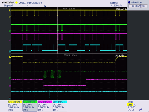
    I post the waveform below instead of cafain.


    There is a specific issue I am seeing with the results.

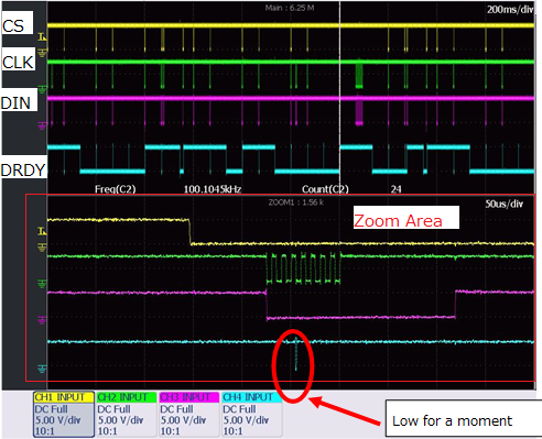
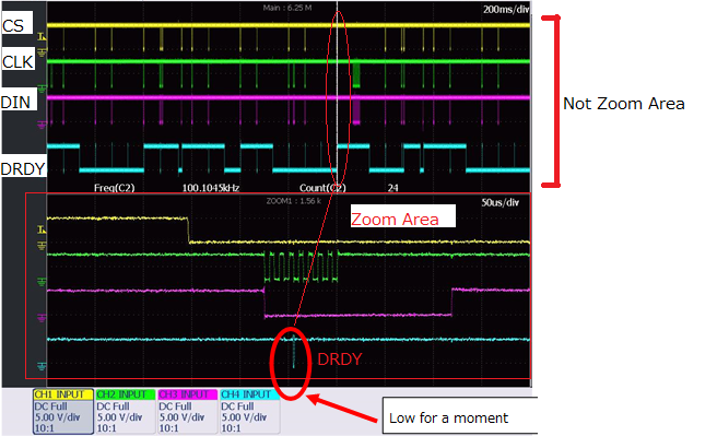
    Red circle focuses that DRDY become low for a moment.

    It is not expected timing. I guess that it caused by DYSYNC command.

    Do you have idea to avoid this?

    When measuring at 200ms cycle, as the measurement start sequence

    1): ACR command (15 Hz setting) : wirte 0x60
        bit 7      bit 6    bit5        bit4         bit3                 bit2          bit1     bit0
        DRDY  U/B     SPEED  BUFEN   BIT ORDER   RANGE   DR1   DR0
        0           1        1            0              0                    0              0         0
    2): Measurement reading (processing to set DRDY to H)
        OP CODE = 0000 0001 (01H)
    3): DSYNC command
        OP CODE = 1111 1100 (FCH)
    4): Dummy clock (start conversion at the first SCLK rising edge
        0x00 1byte sent

    By the way, is it possible to control RESETn pin with RC circuit(10kΩ、0.1uF、5V supply)?

    Best Regards,

    ttd

  • Hi ttd,

    It is not clear to me where the zoomed area is in relation to the not zoomed area on the scope plot.  Can you point out to me the exact area that this occurs?

    When giving back to back commands you must make sure that the command completes before issuing a new command.  For example, you must wait a minimum of 4 tosc periods between sending the DSYNC command and the dummy command (last clock edge of DSYNC command to first clock edge of the dummy command).

    It is also difficult for me to tell what you are doing with respect to command and timing.  It appears that there are a number of DRDY periods that are not read, and clocking and data is sent but they differ from time to time so it is not clear what the command/data sequence is taking place.  I would think that you would see a very uniform response.

    As far as the RESET pin, you can use an RC as long as the logic low period is low long enough after the device starts.  The values you use are most likely not correct.  If you don't want to control RESET by micro GPIO, I would suggest either adding a supervisor to the RESET pin, or tie the RESET pin high and issue the RESET command after power up as opposed to the RC.

    Best regards,

    Bob B 

  • Hi Bob B,

    Thank you for your reply.

    I posted the wave pointed out that zoomed area is in relation to the not zoomed area on the scope plot.

    Could you check below?

    Current Rest time is around 1ms with RC circuit(10kΩ、0.1uF), so I'd try to set more long RESET over 100ms.

    Best Regards,

    ttd

  • Hi ttd,

    What is confusing is the white line is covering over exactly the area of the communication and it doesn't appear to match the zoomed plot.  DRDY is already high in the zoomed plot, but it appears low in the normal plot window.  Based on where the white line is, I would say that the pulse shown is the end of conversion period and would be normal unless the DSYNC command is sent prior.  Can you point out where the DSYNC command takes place on the not zoomed area?

    Thanks,

    Bob B.

  • Hi Bob B,

    Thank you for your reply.

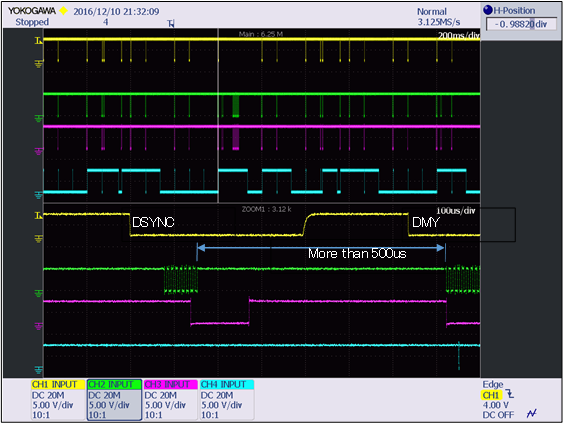
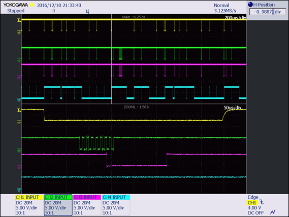
    I attached 3 waveform below.

    Could you chek them?

    ■DSYNC-DUMMY(Yellow:CS Green:CLK Pink:DIN Blue:DRDY)

    ■DSYNC(Yellow:CS Green:CLK Pink:DIN Blue:DRDY)

    ■DUMMY(Yellow:CS Green:CLK Pink:DIN Blue:DRDY)

    Best Regards,

    ttd 

  • Hi ttd,

    Perhaps I'm not clear on what I'm asking to see, but DRDY goes high just prior to the sequence that you show as zoomed.  I need to understand what is happening to drive DRDY high.  Are you reading the conversion results?  What else is happening during this sequence of events?

    Thanks,

    Bob B

  • Hi Bob,


    I apologize that I didn't show the detail of whole command sequence.

    I attached PDF file below. This shows the whole command sequence.

    Measurement reading(2) drives DRDY high before DSYNC command(3).

    Could you check PDF?

    ADS1240_waveform.pdf


    Best Regards,

    ttd


  • Hi ttd,

    This information is a lot more clear.  I do not have access to a lab this week so I cannot verify your timing.  It is interesting to note that there is no DRDY until 2 conversion cycles have completed.  This is not clear to me why this is happening and I will need to investigate further.  I will get back to you as soon as I have more information next week.

    Best regards,

    Bob B

  • Hi ttd,

    Looking through the plots that you've provided, the communications look ok. Based on the plots, the data rate seems to be 15 Hz. With the SPEED bit = 1, and DR bits = 00, the fOSC should be 4.9152 MHz and the fMOD should be 19.2 kHz. Also based on the plots, the SCLK period is about 10us, so the communications should be slow enough for the device to read everything clearly. I'm verifying the timing, so if there's anything that isn't correct, let me know.

    However, I did have some extra questions about the problem. When you see the momentary /DRDY low, how narrow is the pulse? I noticed from two different plots that the momentary /DRDY low seemed to occur at the same place (between the third and fourth SCLK low during the dummy write after the DSYNC command). Does this momentary low always occur here? How often does this occur?

    At this point, I'm not sure what the problem is. Can you change your program to disable the interrupt during the DSYNC command and the dummy write? It might be useful to know if the problem goes away.

    Joseph Wu

  • Hi Joseph Wu,

    Thank you for your reply.

    >Looking through the plots that you've provided, the communications look ok. Based on the plots, the data rate seems to be 15 Hz.
    >With the SPEED bit = 1, and DR bits = 00, the fOSC should be 4.9152 MHz and the fMOD should be 19.2 kHz.
    ⇒You're correct.

    >Also based on the plots, the SCLK period is about 10us, so the communications should be slow enough for the device to read everything clearly.
    ⇒How is the frequency do you recommend under 10us(100ksps)?

    >When you see the momentary /DRDY low, how narrow is the pulse?
    ⇒I'll check it, but it seems that the pulse of /DRDY is under 5us(half of SCLK).

    >I noticed from two different plots that the momentary /DRDY low seemed to occur at the same place (between the third and fourth SCLK low during the dummy write after the DSYNC command).
    ⇒Dose it means the red circle below?
     e2e.ti.com/.../2553.wave.png
     I'll check it.

    >Does this momentary low always occur here? How often does this occur?
    ⇒48 times in about 24,000 (80min operating)

    >Can you change your program to disable the interrupt during the DSYNC command and the dummy write?
    ⇒Does it mean that CPU ignores the pulse of /DRDY during the DSYNC command and the dummy write?

    Best Regards,
    ttd
  • Hi ttd,


    I'll post a few responses to your questions.

    - The SCLK frequency of 100kHz is fine. When I first started looking at the question, I was worried that you had exceeded the max SCLK rate. With a master clock of 4.9152MHz, the max SCLK rate would be about 1.23MHz. I would keep the same SCLK rate.

    - For the momentary /DRDY low, I think the low pulse is much less than 5us. Verify the width of the pulse just to check it. Since the event is rare, it might not be easy for the scope to capture it with such fine resolution. However, let me know approximately the width of the pulse.

    - When I asked about disabling the interrupt during the DSYNC command yes, the CPU would ignore the pulse of /DRDY during the DSYNC command and the dummy write. You would read data out, set the CPU to ignore /DRDY indications, write the DSYNC command, write the dummy, and set the CPU to check /DRDY again.


    Joseph Wu
  • Hi Joseph Wu,


    Thank you for your reply.


    After ADC's conversion finished for 66.73ms, it starts next convesion automatically.

    200ms is about 3 times of 66.6ms, I guess that next conversion and DSYC command are overlap internally at the sametime.

    If DSYNC command and conversion timing are overlap, is it possbole to cancel the conversion?

    If you have a workaround, please let me know.


    I commnet your suggestion below.


    DRDY pulse width is around 8us.


    I think problem is that conversion is canceled and conversion time is 134ms.

    Correct conversion time is 66.73ms.

    CPU is porling for capturing /DRDY.(Not interrupt)

    So it is difficult for solution to ignore /DRDY during the DSYNC command and the dummy write


    Please check page.7 and page.8 on attached file below

    ADS1240_waveform_2.pdf 


    Best Regards,

    ttd

  • Hi ttd,


    It looks like the problem comes when the expected /DRDY comes at 2x the data period. I have a few more questions to add to the last set.

    First are there any other devices on the SPI? I can see a few cases where SCLK is being clocked, but /CS is low. Are there any other devices tied to /DRDY? When the /DRDY fails to go low at the right time, what does the MCU do? There are many SCLK and DIN pulses without /CS, so there must be some other communication.

    When the part is started, was there a STOPC command issued at the beginning so that the data only comes out with RDATA? The figure on page 2 shows that there is a read, but since you don't show DOUT, I'm not sure what the output is. It might be nice to have this information if you had a logic analyzer. However, the device does take /DRDY high at the end of the read, which is what is supposed to happen.

    I'd like to change the measurement sequence. When /DRDY goes low. start by reading back the data. It would be nice to do that as soon as the /DRDY goes low. If you can, increase the polling rate for /DRDY. Then write the ACR to the correct value. Then perform the DSYNC and add the dummy clock.

    Even better, I would like to remove the ACR write completely. If this doesn't change, I would set this once and not repeatedly rewrite this in case there's some glitch in the ADC write into the ACR. In this case, it would start with /DRDY going low, then read the data. When the device is ready for the next read, send the DSYNC command and then issue the dummy byte. I think this would be important to try. If there is a problem with how the ACR is written, this keeps the ADC in the same mode so that the /DRDY should come out at the correct period.

    I mentioned increasing the polling rate for /DRDY. I was concerned that if you had tried to read data at the same time a new conversion was completing, there might be a problem in the data read cycle. I don't think this type of problem is likely, but I thought I'd mention it.

    I've talked to one of the designers, and it appears that /DRDY only rises with the completion of a data read (either 24 SCLKs for RDATAC mode, or RDATA plus 24 SCLKs when in STOPC is issued) or when a calibration command is issued. That being said, it looks like there's a narrow pulse for /DRDY, and I can't see where it's coming from. It it possible that the glitch comes from something else (maybe the MCU or another device)?


    Joseph Wu