This thread has been locked.

If you have a related question, please click the "Ask a related question" button in the top right corner. The newly created question will be automatically linked to this question.

DAC0800: DAC0800 "0V" for "127" input and "5V" for 0 input

Part Number: DAC0800

Can you tell me more about this device. I am trying to output a digital signal (8-bit) to the DAC and get the corresponding analog signal. When I output "127", I get "0V" from the DAC, when I output "0", I get "5V" from the DAC. Is this do to the formatting? I couldnt find it in the datasheet, can you please tell me what the formatting is? Why isnt it a simple binary format? Is there any way to change the reference voltage to "0V" and "5V" instead of "0V" and "10V", so I get "5V" when I input "255" to the DAC?

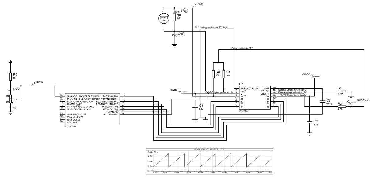
I have made a circuit with PIC16F690 and DAC0800 (its in the attachments), but I get a bad result from the DAC as output voltage. For "127" output from the MCU I get "0V", for "0" I get "5V". The idea is to sample a signal from the in-built ADC and output the same signal to the DAC. The ADC and MCU part are working OK. But can someone tell me, why do I get this error from the DAC? Like this when I increase the ADC input, the DAC output gets decreased and when I decrease the ADC input, the DAC output gets increased.

I can solve it by coding, but I want to know is this the proper way and what am I mistaking? I used the datasheet to build the circuit.

Vref+ = 10V
Vref- = 0V
V+ = 36V
V- = -36V
THRSH control pin = ground so I can use TTL logic.
B1 (DAC PIN) = MSB (RC7 on PIC16F690)
B8 (DAC PIN) = LSB (RC0 on PIC16F690)

The analog peripherals of the MCU are disabled in order for the PINs RC0, RC1, RC2 to be used as digital (comparator, comparator, CVref).

Can anyone help me please?

Circuit:
  • Hi Arakel,

    Thanks for using the e2e forum, let's see if I can shed some light on some of the issues you are having.

    The first thing I noticed with your design is that you are powering the DAC with +/-36V.  This far exceeds the maximum supply ratings of the device.  Maximum bipolar supplies for this device is +/-18V or unipolar 36V.  I recommend that you reduce the supplies first, and please consider that this device could be damaged while you are doing your debug.

    Secondly, recall that for the DAC0800 the sum of the two IOUT pins is always IFULLSCALE, or VREF/REF.  As you are grounding pin 2, /IOUT, table 1 in the DAC0800 datasheet best describes you operation.  When you have the DAC set to code 0x00, the IOUT (pin 4) is not sinking any current.  When you have it set to 0x80 it is sinking 1/2 the IFS, etc.  Let's simplify the output stage of your schematic for a easier way to look a this:

    The output stage you have created is essentially a resistor divider from you 10V 'pullup' resistor and your resistor to ground.  IS1 represents the DAC IOUT pin which is sinking current.  At 0x00, the pin is not sinking anything and the output is just a resistor divider with 5V measured across R1.  When the output is at 0x80, the DAC is sinking approximately 1mA, pulling current from the divider and lowering the voltage across R1 to approximately 0V.

    Let me know if you have more questions, I would be happy to help!

    Thanks,

    Paul 

  • I will check how to fix this, but for the supply voltage the datasheet says +-18 ot +-36.
  • Hi Arakel,

    The datasheet specifies that the absolute max voltage can be +/-18V or 36V. Meaning that you can use 0V for the V- supply and +36V for the V+ supply.  The total potential between the V+ and V- should not exceed 36V in any configuration.

    Please let me know if you have any more questions,

    Thanks!

    Paul

  • I thought that was +-18 or +- 36. I will try with "36" and "0".