This thread has been locked.

If you have a related question, please click the "Ask a related question" button in the top right corner. The newly created question will be automatically linked to this question.

TLC2543: EOC signal stays low beyond the specified time

Part Number: TLC2543
Other Parts Discussed in Thread: TLV2556

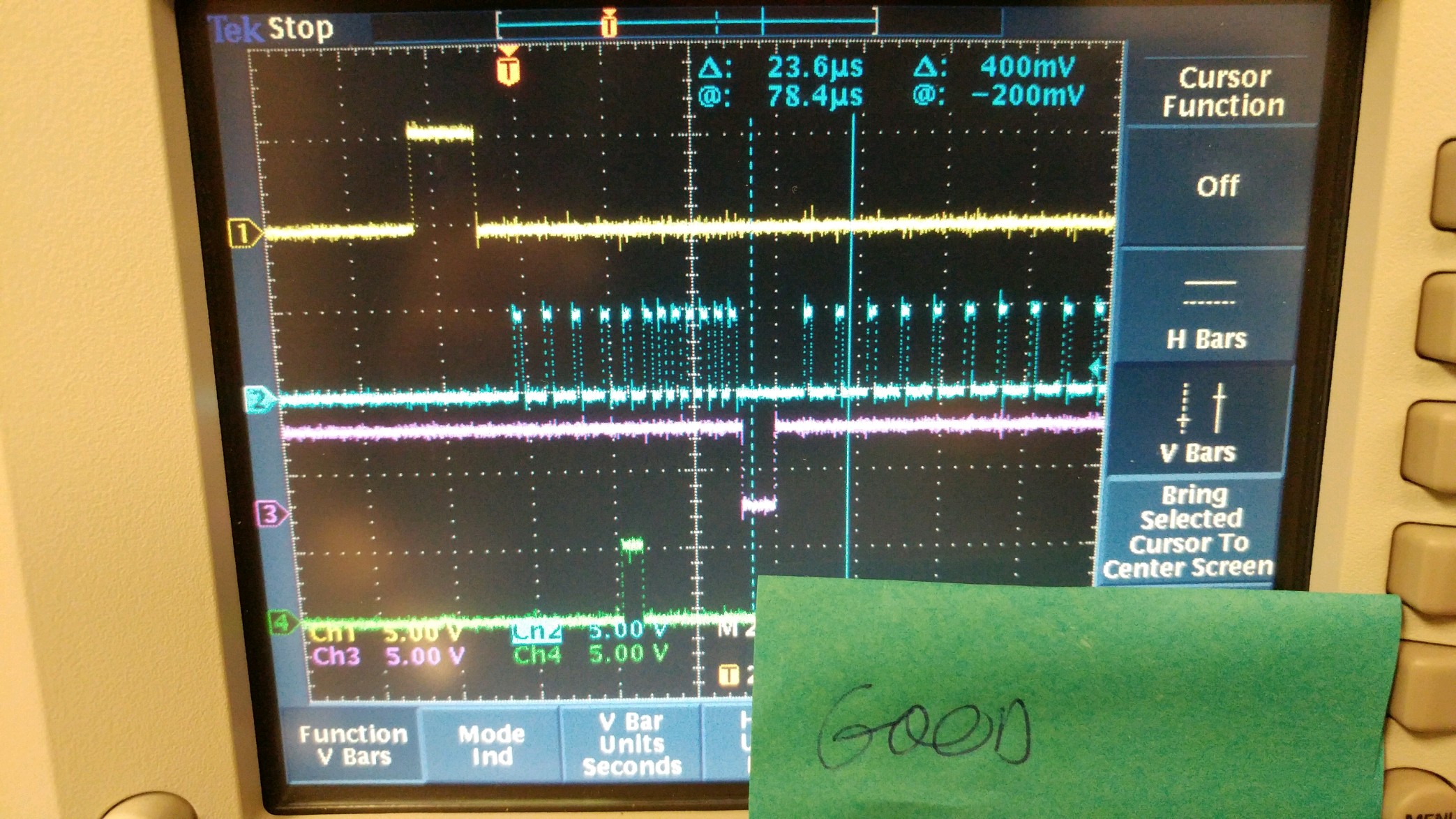
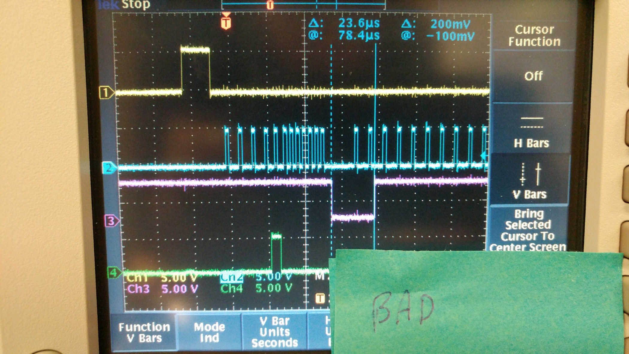
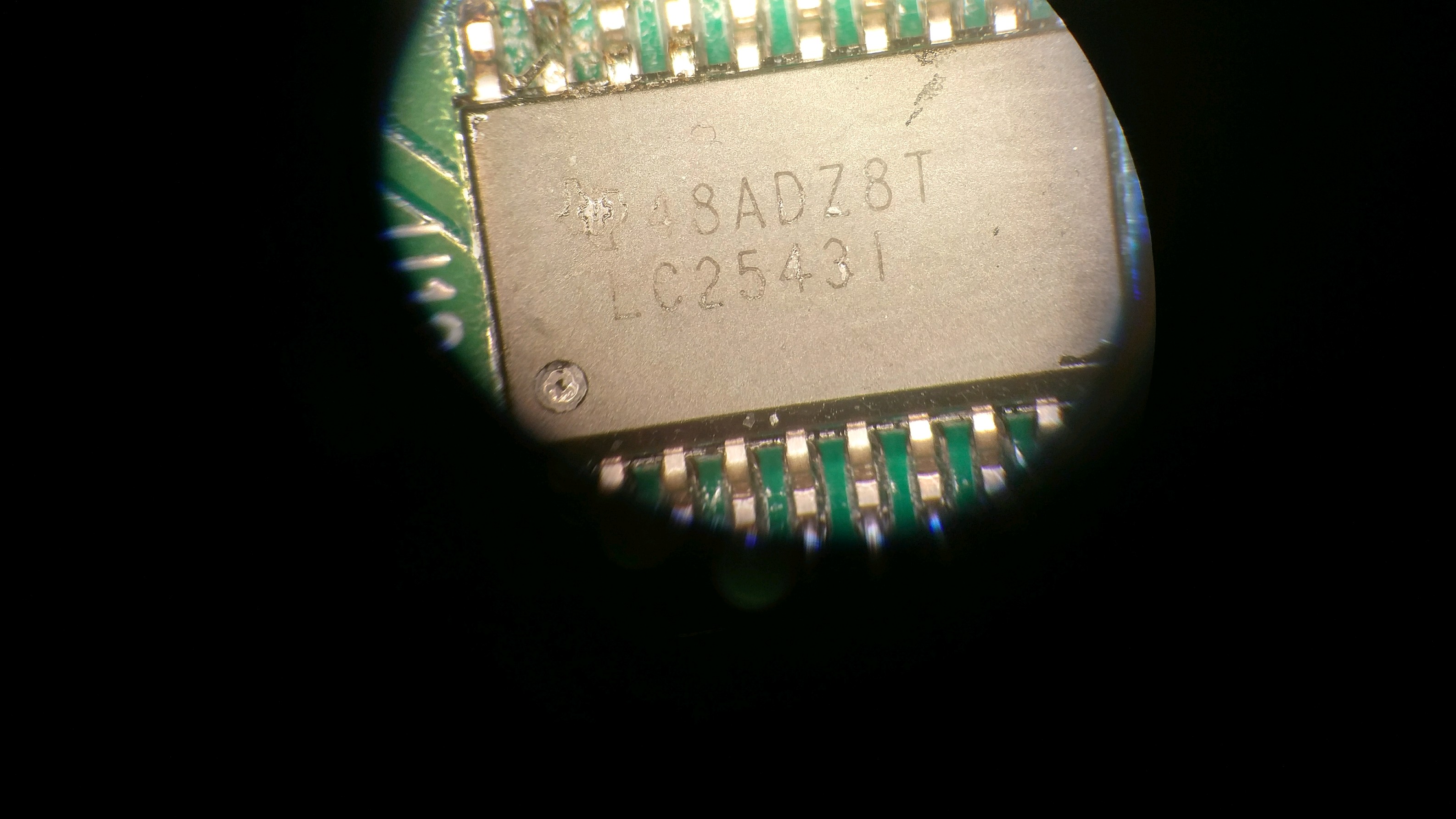
We are having to replace the TLC2543 parts on a regular basis to get our product to work. I have taken a look at the part and notice that upon initialization the part will either operate correctly or sometimes (tends to be worse at colder temperatures on affected parts) the part looks to operate normally except the EOC signal stays low for 23us which is far beyond the specified maximum of 10 us. Once the EOC goes low for 23 us , then it stays at 23 us every single time that EOC goes low. Also , if the EOC is correct, then it is always correct.  This is causing our system to hang up.  I have attached a scope traces of a good EOC signal and a bad one.  Why is the EOC signal going past the 10 us maximum?  Any suggestions to keep EOC in spec under all conditions?

Yellow = CS

Blue = Data

Pink = EOC

Green = address

  • Hi Brent,

    Just to make it clear for me, when you say address (green trace) this is data input to the TLC2543? If it is, it looks like you are sending 0x10 (read AIN1, 12 bits, MSB 1st, binary). Also, it looks like you are doing your transfer not using CS, as is shown in Figure 10 in the datasheet. Is that correct?

    Could you describe for me your initialization sequence, what codes you send to the part after applying power?

    Also, could you show me the same pictures but also showing the clock? You could replace the signal on the green trace.

    Thanks,

    Mike
  • Hi Brent,

    Could I also get the date code of the device?

    Thanks,

    Mike
  • The blue trace is the clock, I misstated that above.  What is shown there is the first clock capture after power up. 

    This design has been in production for approximately 20 years and production is now replacing approximately 30% of these parts on factory test (mostly at cold temperature - although the one I am showing you exhibits this phenomenon at room temperature). 

    My belief is that figure 10 represents our approach.  I believe that the data for a particular analog channel is captured by sending two 12 bit bursts of clock in while CS is low and that the desired channel selection and reading is taken on the first burst and then the data is read off of the second burst of clocks.  After the data is read then the process repeats for a different channel selection.  Also, our design spaces the time between the two burst based on the minimum set up and conversion times stated in the data sheet, so when the EOC overruns, then the process is broken.

    Shown below is the photograph of the part.  We conformal coat the parts and there is a little residual coating on this part.

    Also, I am looking at possibility of substituting the TLV 2553 or TLV2556 if I cannot get this to stop.  Are these parts good alternatives?

  • I meant that it spaces the clock bursts based on the **maximum** set up and conversion times.
  • Is this problem still being reviewed by the application engineers? 

  • Hi Brent,

    Sorry for the delay.  Could you contact me at mike.stout@ti.com? 

    Thanks,

    Mike