This thread has been locked.
If you have a related question, please click the "Ask a related question" button in the top right corner. The newly created question will be automatically linked to this question.
Hi ,
I have used the part ADS1014 to measure the Li-ion battery voltage level(4.2V) . It is worked fine and we have done production of 50 boards as initial build. out of 10 boards two boards get failed . In one board ADC read value is 600mV when the voltage at analog input pin 4.2V . In another board, ADC read value is 4.9V when voltage at analog input mode is 4.2V
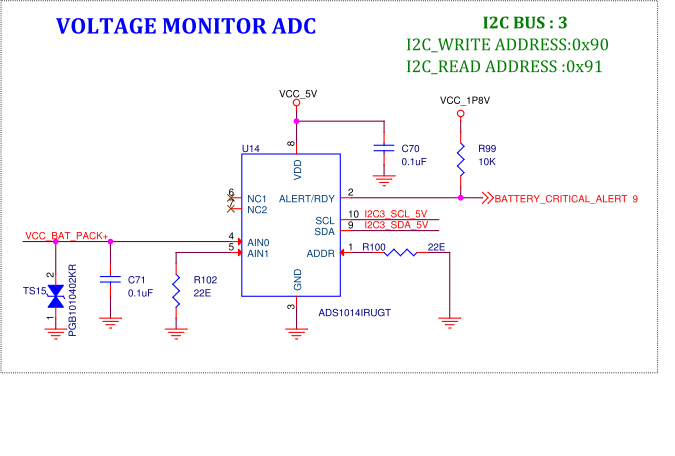
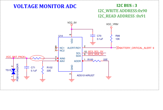
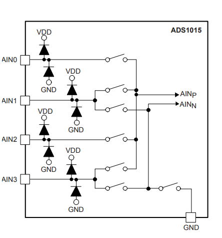
I have configured to use in single ended mode and FSR is set 6.144V. I have used the TVS diode and 0.1uF at the analog input pin to for ESD and transition production. I am not clear what is happening inside the chip. we are started to deliver this product to our end customer. can you please help to fix this issue ASAP.
Below is the snapshot of the schematics. VCC_BAT_PACK+ is coming from the Li-ion battery and its maximum voltage is 4.2V
Tamilarasan,
I'm not sure what the problem is, but I do have some recommended things to check.
First, It it possible that the device has experienced an over-voltage or ESD event? I mention this because looking at the TVS diode, you're not really protecting the device. The reverse breakdown of the TVS is 12V. At 12V you'll have already blown up AIN0. To protect the device, you'll still need some series resistance on the input to limit the voltage and current going into AIN0. To do this you'll need to do something like the diagram shown below (with resistor circled in red).
Alternately, you could use the same TVS, but then use a voltage divided version of the battery for measurement. This would also limit the input voltage and current seen by the device. An example is shown below:
After considering ESD, I would check the R102 connection to see that AIN1 is really connected to ground. There may be some problem with a ground loop voltage. It is unlikely that a ground loop would be so bad to cause such large errors. Regardless, check it just to be sure. Whenever ADC measurements are returned incorrectly, I measure the inputs directly with a multimeter. Also, I would check the I2C communications. Grab the SDA and SCL lines with an oscilloscope or logic analyzer and check them. Post them back here if there are issues.
Also, I would read back the registers. If you have a system that is mis-programmed, you might have an error like this. I would guess that this is also unlikely, but you'll need to check it.
For the failing systems, do they recover after the power is removed or do they consistently give the same bad values?
Read through my comments and let me know if you have any questions.
Joseph Wu
Hi Joseph
Thanks for the reply.
Regarding TVS diode, there is an another 5V Reveres breakdown voltage TVS diode , SMF5.0A parallel to ADC_IN pin at battery connector end. And I am sure that there is no issue with the i2C read and write since it worked well during our prototype development ( ~20 boards).
I also understand that adding series resistor only limit the input current to ADC_IN pin. Since this boards are started to deliver, I want to understand the probability of failure of shipped boards due to aging and environmental impact. do you have any idea about the internal integrated ESD production diode electrical spec like max forward current, reverse break down voltage. Also please let me know is there any drop in replacement chip with integrated Series / voltage divider options?
Thanks,
Tamilarasan
Tamilarisan,
I don't have much guidance for the ESD diodes ratings. They are there to help with specific ESD tests. For the ADS1014, the device is rated to ±2000V HBM and ±500V CDM according to the JEDEC standard.
Beyond that, I would look to the Absolute Maximum Ratings table in the datasheet. This is Section 7.1 on page 5. There, it says that the maximum continuous input current is ±10mA for any pin (other than supply pins). This should define the maximum sustained input/output current for the device without damaging it. Also, the maximum and minimum voltages for the device are listed as VDD+0.3V and GND-0.3V respectively. This also outlines the maximum/minimum for the pins without damaging the diodes.
To be clear, are you still having problems with bad read values? Or have you solved that particular problem?
Joseph Wu