This thread has been locked.

If you have a related question, please click the "Ask a related question" button in the top right corner. The newly created question will be automatically linked to this question.

TINA/Spice/DAC101S101: Data Output Problem using DAC101S101

Part Number: DAC101S101
Other Parts Discussed in Thread: TINA-TI,

Tool/software: TINA-TI or Spice Models

Hello 

i am new member and new to DAC101sS101.

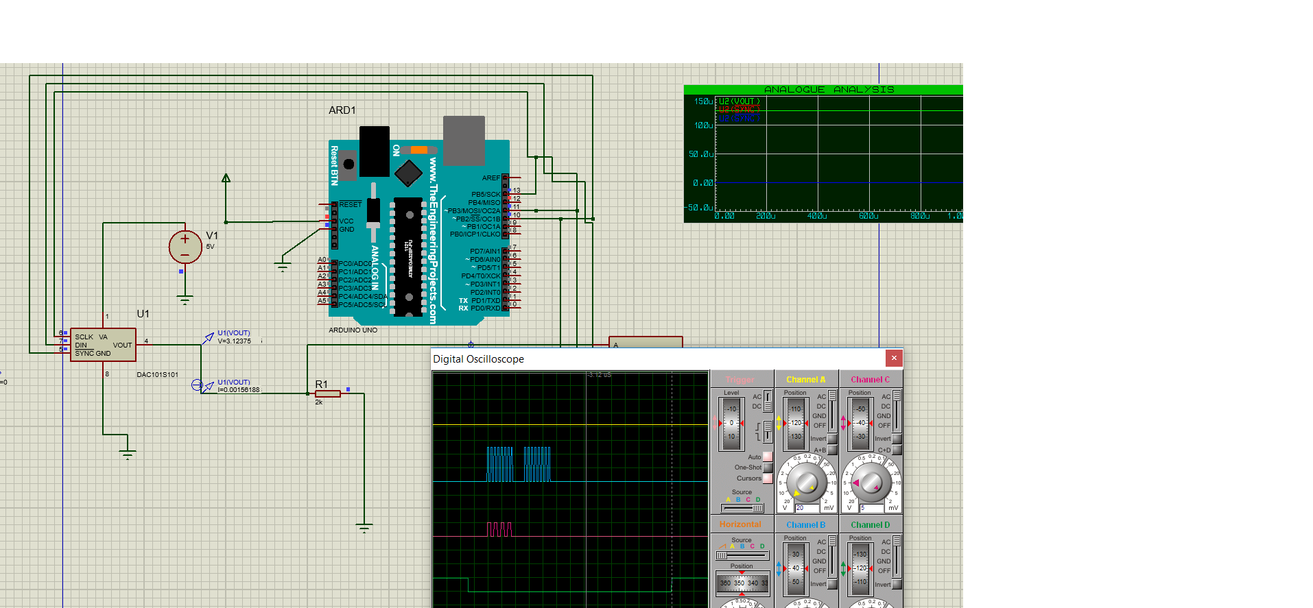
i am  using DAC101S101 with Arduino SPI but the problem is i am not getting the data at output which has been sent as an input.

forexample through arduino code i am entering SPI.transfer16(oxaa00) which means it should give me output of 4.88*(160/1024)=0.76v

but instead i am getting 3.79v

will this forum helps me to have a test code or something i might be doing wrong.

i will be really thankful.

  • Sarmad,

    Welcome to the E2E Community. We will try to track down the root cause of your issue to solve this problem.

    Hex data 0xAA00 in binary is 10101010-00000000. The data format in the datasheet describes two don't care bits, followed by two power-down bits, then 10 DAC data bits, and finally two don't care bits. Referring back to your input data of 0xAA00, that breaks down to 10-10-1010000000-00. That pattern should place the device in power-down mode with 100kOhm to GND and the rest of the device disabled but with decimal 640 in the data register. I am not sure how 3.79V is still appearing on the output as the device should be in power-down mode.

    What is missing from the data provided so far which could explain how the device is behaving in an unexpected fashion are the clock phase and clock polarity configurations of your Arduino SPI bus. Using clock polarity 0 the clock phase should be configured as 0 as well as data are clocked on the rising edge of SCLK. Using CPOL = 1, CPHA should be 1 as well.

    Perhaps you can provide an oscilloscope capture of the SPI bus transaction and we can sort out what's going on.
  • Hi

    Thank You so much for help it was really urgent.

    Please find below the required configuration in Proteus 8.Once i set the polarity to SPIMODE-1 which has required characteristics as you mentioned

    it is giving me correct output. Decimal 640 means Vout=5*(640/1024)=3.1v. please check and confirm whether it is ok now?

    and also if i want to send two different bytes through SPI to DAC how it can be done?

    Can you please help me out this issue as well.

    i shall be very thankful to you.

  • Also
    it is giving me outputs for large decimal numbers like 5000 etc which will cross it limits.
    but when i enter decimal number between 0-1023 its not working.
    please help me out.
  • Sarmad,

    Unfortunately I do not really understand either of your questions.

    Your first question concerning sending multiple bytes would appear to have already been solved as the SPI communication frame is 16-bits wide, or two bytes.

    Concerning the second question, your first post appeared to suggest you had communication successfully established and were communicating with the DAC with expected results. What changed? Can you again describe the exact contents of the SPI frame versus just a decimal number?
  • Kevin,

    i am sorry let me explain the situation.

    yes you are right regarding your first question the problem has been solved.

    My second question is related to below situation.

    I am trying to make SAR ADC with arduino and using DAC101S101.

    Please find attached SAR ADC schematic.

    and below is my code which i am trying to achieve with help of Arduino and DAC101S101 and a comparator.

    for(int i=9; i>=0; i--)
    {
    SAR = SAR | ((uint16_t)1 << i);

    // set current DAC output 
    digitalWrite(SS, HIGH);
    digitalWrite(SS, LOW);

    byte mode = 0b00000001;            //put the mode number here. 

    byte firstbyte=(mode << 4)|(SAR>>6);   // making it exactly like 2 bits dont care-10 power down mode -10 bits -10 2 bits dont care
    byte secondbyte=SAR<<2 ;


    SPI.transfer(firstbyte);
    SPI.transfer(secondbyte);

    digitalWrite(SS, HIGH);


    Please correct me if i am sending the data from SAR to DAC wrongly.


  • Sarmad,

    What is the resolution of the SAR ADC? I guess you are receiving data from the SAR that is of greater resolution than that of the DAC since you've suggested you have data "5000" decimal to work with. You'll need to bit-shift or otherwise translate the data from the SAR into the correct format and resolution of the DAC.

    It would appear you have successfully communicated with the DAC. The problem before you now seems to be more of a system or product level topic for what you are developing.
  • Kevin,


    Thank you so much for your help and kind reply.
    You are really very helpful.

    Yes, i am successful in communicating DAC with my Micro controller.
    My SAR ADC resolution is 10 bits.
    Yes, i am getting some results which is not up to the mark. Yes you are right, as in my previous mentioned post, the code for bit shifting or
    translation is right for our DAC101S101 or not?

    My SAR is 16 bits as we need it, the only change i can do is in Shifting data in proper format i believe.
    Kindly help me out in sending proper format Data from SAR to DAC101S101.
    I shall be very thankful to you for this act of kindness.

    Sarmad
  • Sarmad,

    To this point I don't know anything about the SAR ADC or it's output data format so it is not possible for me to provide you any guidance on this translation. If it's a straightforward 16-bit SPI transaction with 16-bits of data then this needs to be shifted such that the bottom 6 LSBs are truncated before it is communicated to the DAC. Given that the 2 LSBs in the SPI transaction to the DAC are don't care bits you could get away with just a 4 bit shift.

  • Kevin,
    Thank you so much for your kind reply and your assistance.
    i will work this thing out nonetheless you started my DAC101S101 communicated.

    Thank you

    Sarmad
  • Kevin,

    Can you please explain the difference between normal mode and power down modes
    of DAC101S101 ?


    Sarmad
  • Sarmad,

    This is explained on bottom of page 18 and first two paragraphs of page 19 of the datasheet. Do you have a question that goes into further detail than what is described on the pages?
  • Kevin,
    Thank you so much for your reply .

    Yes i have read that portion of datasheet but i am asking as when i provide 512 decimal in binary 01-00-1000000000-00 it should give me output of
    2.5 as Va is 5 v in my case rather it gives me 1.25.
    i have checked it with SPI debugger as well and Data input is in correct order as mentioned.
    but when i provide Va = 10 v i get 4 v at output and gives me correct output but the problem is MAx voltage Va should be below 6.5 v.
    can you please help what should i do in this situation?
    My SPI is 8 MHZ MSB First while Cpol=1 and Cphi=1.
  • Sarmad,

    I think I eluded to the modes you were configuring the device for in my first post regarding the leading two MSBs. With binary 01 in these two bits the device is set to power-down mode with 1kOhm to GND output impedance at the VOUT pin. Additionally, according to the datasheet, the internal bias generator, output amplifier, resistor string, and all other linear circuits are in power-down mode. The MSBs should be 00 to be configured in normal operation.

    I also just noticed that when I initially suggested clock polarity and phase settings that was based on the text of the datasheet, which includes an inverter on the SCLK lines. Data is actually read on the falling SCLK edge per the timing diagrams on pages 9 and 10. So CPOL = 0, CPHA = 1 or CPOL = 1, CPHA = 0. Sorry for that confusion, I'm not sure why this datasheet includes so many different explanations of the SPI interface timing in the text.