This thread has been locked.

If you have a related question, please click the "Ask a related question" button in the top right corner. The newly created question will be automatically linked to this question.

ADS1255: SPI connection to ADS1255

Part Number: ADS1255
Other Parts Discussed in Thread: ADS1256

Hi there,

For a few days I'm trying to communicate to the ADC on my board. As a µC I'm using a Atmega168 and its Hardware SPI Pins. I've already tried different SPI-Modes but without success. At several places on the net i read that the time interval between DIn and DOUT (t6) is very critical. So i added a delay of 50 µs in my SPI-transceiver method.

I thought i could start simple and try to read out the STATUS-register of the chip. So i sent the commands to the chip. Problem is i am always reading back "0xFFFFFFFF" even if i change the register to be read to DRATE or something else. So thats not valid. I'm new to this kind of ADC communication so maybe i am doing something completely wrong.. I will add my code here maybe someone instantly could identify some mistakes. I'm not using the external interrupt for !DRDY yet. In the main-loop i am only reading the status register at 1000ms intervals.

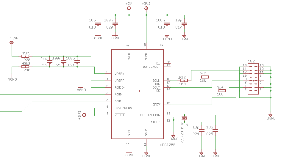
The scematic of the chip is according to the dataseet page 28. Thank you very much

#define BAUD 115200UL
#define UBRR0_Value (F_CPU/(16*BAUD)-1)

#include <avr/io.h>
#include <util/delay.h>
#include <avr/interrupt.h>
#include <string.h>
#include <stdio.h>
#include <stdlib.h>


static void uart_transmit_char (unsigned char ch)
{
	while (!(UCSR0A & (1<<UDRE0)))
	{
		;
	}

	UDR0 = ch;
}

static void uart_transmit_string (char * s)
{
	while (*s)
	{
		uart_putc (*s);
		s++;
	}
}


char UART_receive(void){
	while(!(UCSR0A & (1<<RXC0)));
	return UDR0;
}


void UARTinit(){
	UBRR0H = (unsigned char) (UBRR0_Value >> 8);
	UBRR0L = (unsigned char) UBRR0_Value;
	UCSR0B = (1<<TXEN0) | (1<<RXEN0);
	UCSR0C = (1<<UCSZ00) | (1<<UCSZ01);
	
}

void spi_init()
{
	DDRB = (1<<5)|(1<<3)|(1<<2);			 // MOSI, !CS , SCK as Output
	SPCR = (1<<SPE)|(1<<MSTR)|(1<<SPR0);     // SPI Enable, SPI = Master, Prescaler = 16
}  

unsigned char ADS1255_transceive (unsigned char data)
{
	SPDR = data;           
	while(!(SPSR & (1<<SPIF) )); 
	_delay_us(50);					// wait for 50µ until DOUT (t6)
	return(SPDR);                      
}

char ADS1255_Read_Status(){
	
	char ans;						// Return variable 
	
	PORTB &= ~(1 << PORTB2);		// !CS = LOW  
	_delay_us(10);
    ADS1255_transceive(0x10|0x00);   // Send RREG command (Status)
	_delay_us(10);
	ADS1255_transceive(0);           // read one register
	_delay_us(10);
	ans = ADS1255_transceive(0);     // send Dummy-Byte and save return value
	_delay_us(10);
	PORTB |= (1 << PORTB2);			// !CS = HIGH
    _delay_us(10);
	
	return ans;
}

int main(void)
{
	
	 char test;
	 
	 DDRD &= ~(1 << 2);    
	 PORTD |= (1 << 2);     
	 EICRA |= (1 << ISC00) |(1 << ISC01);  
	 EIMSK |= (1<<INT0);				   //  external Interrupt (!DOUT) at INT0	


	UARTinit();							   // UART 
	spi_init();							   // SPI
	//sei();
	
    while(1)
	
    {     
		test = ADS1255_Read_Status();
		uart_transmit_char(test);
		_delay_ms(1000);
    }
}

ISR(INT0_vect){
	
 // !DOUT-Interrupt
}

  • Hi Daniel,

    Before you get too far into debugging your code, I might double check to see if the crystal connected between pins 12 and 13 is oscillating (by probing with an oscilloscope). If this crystal is not oscillating then you won't get any responses from the ADC; therefore, try checking that first...

    The next thing I would do is probe the SPI pins to see if your commands are being transmitted and that /CS is being set correctly. If not then perhaps something about the SPI peripheral is not configured correctly.

    ...Those are probably the most likely reasons why you wouldn't get a response back from the device.

    Looking through you code, the only thing I would recommend is to insert an SDATAC command before reading or writing to the ADS1255 device registers. The ADS1255 needs to be in SDATAC mode in order to access the registers. I believe SDATAC is the default mode after start-up, but it is best practice to issue this command and not assume that the device defaults to that mode.

    Best regards,
    Chris
  • Hi Christopher,

    thank you for your answer. I did the steps you recommended to me. I checked the Crystal and it is oscillating just fine as you could see in the first picture. Its a 7.3728 MHz Crystal so also the frequency looks good.

    Next i probed the SPI Pins. My board ist configured as a stacked PCB i am not able to measure directly at the Pins. So i had to measured at the pinheaders which are connecting the to boards. But  beside the three resistors in the input lines there is nothing between the measuring points and the pins of the chip.

    I added the the SDATAC command and also a wakeup command before i am trying to read the status register. The following pictures are showing the recorded SPI lines. All the three commands cam be seen on the pictures. I think the signals are looking okay so far. But no matter what i do the DOUT Line stays quiet as you can see in the last picture. I can only record to channels so i did three different picures. On every picture channel one (yellow) is showing the !CS line. First picture channel two ist the DIN line and second the SCK line. What do you think? Thank you very much.

  • Here is the code.


    #define BAUD 115200UL #define UBRR0_Value (F_CPU/(16*BAUD)-1) #include <avr/io.h> #include <util/delay.h> #include <avr/interrupt.h> #include <string.h> #include <stdio.h> #include <stdlib.h> // Send char via UART //__________________________________________________________ static void uart_transmit_char (unsigned char ch) { while (!(UCSR0A & (1<<UDRE0))) { ; } UDR0 = ch; } // Send string via UART //__________________________________________________________ static void uart_transmit_string (char * s) { while (*s) { uart_putc (*s); s++; } } // Receive Byte via UART // _________________________________________________________ char UART_receive(void){ while(!(UCSR0A & (1<<RXC0))); return UDR0; } // Configure UART //__________________________________________________________ void UARTinit(){ UBRR0H = (unsigned char) (UBRR0_Value >> 8); UBRR0L = (unsigned char) UBRR0_Value; UCSR0B = (1<<TXEN0) | (1<<RXEN0); UCSR0C = (1<<UCSZ00) | (1<<UCSZ01); } // Configure SPI // ________________________________________________________ void spi_init() { DDRB = (1<<5)|(1<<3)|(1<<2); // MOSI, !CS , SCK as Output SPCR = (1<<SPE)|(1<<MSTR)|(1<<SPR0); // SPI Enable, SPI = Master, Prescaler = 16 } // Send SPI Data and return the return byte //________________________________________________________ unsigned char ADS1255_transceive (unsigned char data) { SPDR = data; while(!(SPSR & (1<<SPIF) )); // Wait until transmission complete _delay_us(20); // wait for 20µ until DOUT (t6) return(SPDR); } // Read Status-Register of ADS1255 // _______________________________________________________ char ADS1255_Read_Status(){ char ans; // return value PORTB &= ~(1 << PORTB2); // !CS = LOW _delay_us(20); ADS1255_transceive(0b10|0x00); // Send RREG command (Status) //_delay_us(10); ADS1255_transceive(0); // read one register //_delay_us(10); ans = ADS1255_transceive(0); // send Dummy-Byte and save return value // _delay_us(10); PORTB |= (1 << PORTB2); // !CS = HIGH _delay_us(20); return ans; } int main(void) { char test; // External Interrupt for !DRDY //_______________________________________________- DDRD &= ~(1 << 2); PORTD |= (1 << 2); EICRA |= (1 << ISC00) |(1 << ISC01); EIMSK |= (1<<INT0); // Start UART and SPI //_______________________________________________ UARTinit(); spi_init(); _delay_ms(500); // wait for 0.5 sec // Send SDATAC Command //____________________________________________ PORTB |= (1 << PORTB2); _delay_us(20); PORTB &= ~(1 << PORTB2); // !CS = LOW _delay_us(20); ADS1255_transceive(0xF); // SDATAC PORTB |= (1 << PORTB2); // !CS = HIGH _delay_us(20); //___________________________________________ //sei(); while(1) { // senbd WAKEUP command //__________________________________________________ PORTB &= ~(1 << PORTB2); // !CS = LOW _delay_us(20); ADS1255_transceive(0); // Send WAKUP PORTB |= (1 << PORTB2); // !CS = HIGH _delay_us(20); // read status register every second //_____________________________________________ test = ADS1255_Read_Status(); // Send RREG command (Status) uart_transmit_char(test); // Send register value via UART _delay_ms(1000); // wait 1 sec } } ISR(INT0_vect){ // !DOUT-Interrupt }

  • Hi Daniel,

    You should be getting some kind of response from the device when sending SCLKs. No activity on DOUT probably means there is a hardware-related issue somewhere...

    Is DOUT connected to anything else in your circuit that might be pulling it low?

    Do you have the AGND and DGND pins of the ADS1255 connected together?

    Is your MCU connected to the same ground as the ADC? Is the MCU operating off of the same digital supply voltage (so that logic levels are compatible)?

    Are one of the /PDWN or /RESET pins on the ADS1255 being held low?

    Best regards,
    Chris
  • Hi Christopher,

    DOUT is connected to the MISO Pin of the Atmega and to the ISP-header for programming the µC. But the ISP-connector is just for programming and not connected while testing the ADC. So no, nothing else is connected to that pin.

    I have seperated the AGND and DGND on the PCB, but directly under the ADC they are connected.

    Yes the ground planes of the two boards are connected through the pinheaders. Also the same voltage regulator (3,3V) supplies the µC and the ADC.

    /PDWN and /RESET are constantly tied to 3,3 V. so there is no chance that they are held low. Ich will add a part of my scematics here. The pinheader on the right is connecting to the second board where the µC is placed. Any ideas?  Thank you.

  • Hi Daniel,

    Your schematic looks okay. Generally, I prefer to share a single ground plane for AGND and DGND to ensure that this connection is low impedance, but if you've connected these nets together close to the ADC then you shouldn't have any problems.

    Have you tried replacing the ADS1255 or communicating with another board? Perhaps this device got an ESD zap somewhere and the digital circuitry is just not responding.

    Another health check you can do is probe the /DRDY pin to see if that signal is pulsing at the default 30 kSPS data rate... If the device is powered properly and clocked you should see some activity on /DRDY.

    Best regards,
    Chris
  • Yes i did this before. As you can see in the picture below i am getting these pulses. So the chip seems to be alive.The 28.8 kHz correspond to the datasheet.

    (7.3728 / 7.68) * 30 kHz = 28.8 kHz. Seems fine

  • Hi Daniel,

    If you can, it still might be a good idea to try to communicate with a another device. ESD damage can often just affect certain parts of a device, leaving other sub-circuits functional...

    Also, would you be able to show me an oscilloscope screen with the SCLK and DIN signals? By looking at SCLK and DIN together it will be easier to interpret the commands that you're sending to the ADS1255.

    Thanks,
    Chris
  • Hi Christopher,

    maybe i can try another device. But i have to set up a whole new prototype board for it, because i will be quite hard to desolder just the single device.

    I only have this screen, which ist showing the last part of the command sequence. It shows the SCLK and DIN oft the RREG command for the status register. Otherwise the combination of picture 2 and 3 of my second post showing the whole sequence of SCLK and DIN. Thank you very much again.

  • I just recognized that the SCLK doesn't go down to ground. I dont know why or if that's normal? According to the datasheet of the ADS1255 the amplitude for low level on the digital inputs is 0.2*DVDD. SOoaround 0.66 V. I am not sure but i think the SCLK level is under 0.66 V when on "low"... May this cause trouble? Thanks
  • Hi Daniel,

    That's a good observation, I didn't notice that. However, I almost said something about the same RC time constant-like charging that appears on the /CS signal...

    From what you've shown, I only see 100 Ohm series resistors on the SPI signals, which I wouldn't expect to be large enough to cause these effects. Are there any other components that connect to these signals? Also, it isn't clear to me if your MCU on the same PCB or a separate PCB from the ADC?

    SCLK is a high impedance input on the ADS1255, so I wouldn't expect there to be any issue with driving this signal low. If there is nothing else on this signal that could be pulling it high, I might try to see if I could measure a voltage difference between the ADC's DGND and the MCU's GND to see if perhaps there is some difference in the ground references of these devices.

    Best regards,
    Chris

  •  Hi Chris,

    thank you for your answer.  Sorry if I didn't write clearly about the PCB situation. The ADC and the MCU are not on the same PCB. I made one PCB for the analog circuit and the mix device (ADC). On a second PCB there are the MCU and the voltage regulators.  The two PCBs are connected through pin headers. So the SPI signal is leaving the ADC runs through the pin headers and than straight into the MCU. There is nothing else between it. No other devices except the ISP are connected to the SPI bus.  

    On the schematics I've posted a few posts ago, you can the the pin header connection. On the following picture there is the counter part on the second PCB (MCU). As you can see. Nothing besides the ISP.  The MCU and ADC are placed close to the pin headers on their PCB.

    I also just measured the potential between GND (MCU) and DGND (ADC).  Its 0.00 V. I expected this, because the ground of MCU und ADC are connected through the pin headers.

  • Hi Daniel,

    The connection between PCBs looks okay. You have lots of ground pin connections through the header, so I'm not worried about the grounding there. However, I noticed that their aren't any power supply connections through this header...

    Are you using the same +3.3V supply for both boards? And is the +5V supply referenced to the same ground as the +3.3V supply?

    If you disconnect the two PCBs, is the MCU able to drive SCLK closer to 0V, or might their be an issue with the MCU not driving to 0V?

    Are there any other pins on the MCU that might be souring or sinking a lot of current and interfering with the SPI communication?


    ...Sorry to replay back with a list of questions, but I'm a bit stumped myself as to why you're having issues with the SPI communication.

    Best regards,
    Chris
  • Hi Chris,

    yes you are right. There is an extra header on the side of the PCB for the power supplies. The 3.3 V and 5 V are routed to the ADC PCB through this one. I wanted to have a seperate header just for the SPI communication. Yes there is one voltage regulator (LF33) which supplies both PCBs. But i couldn't measure any voltage drops or something like this. There is not much more than the two voltage regulators, a reset button, and some headers on the MCU PCB. So no big currents. The MCU is just sending out data for debugging via UART. That's all.

    Tomorrow, I can try to probe the SCLK signal again with seperated PCBs. And maybe set up a new board. Because its getting quite frustrating.
    Bye the way.. Is it possible to communicate to the ADS1255 by just connecting the digital part ( 3.3V). This way i wouldn't have to set up all the analog circuit for testing the SPI. Thank you again.
  • Hi Daniel,

    I just did a quick test on the ADS1256EVM and found that I could not communicate with the ADS1256 unless both the AVDD and DVDD supplies are powered.

    Best regards,
    Chris
  • Hi Chris,

    first of all I have good news. The ADC ist working. Shame on me... I've found a solder bridge under the microscope between SCLK (Pin18)  and D0 (Pin19). I couldn't see it by eye or magnifying glass. I didn't measured it yet but i think that might be the reason why SCLK doesn't go down to ground and the ADC doesn't receive a proper clock signal.  Now i can read and write registers without any problems at all. I kept on programming and now try to read data from the ADC. And now i am getting into trouble again. According to the datasheet the ADS1255 is putting out the data in 2's complement. Now i am not sure if  I have to manipulate the data before combining the three bytes together. I read this article

    It’s in the math: how to convert an ADC code to a voltage (part 1)

    TI E2E support forums
    Many newcomers to analog-to-digital converters (ADCs) wonder how to convert their ADC code to a voltage. Or perhaps their question is specific to the application, such as how to convert the ADC code back to a physical quantity like current, temperature...

    and tried the code example, but it's not working as expected. In the article they are not talking about the 2's compliment.

    First i will explain my signal flow a little bit further. I want to measure a thermocouple voltage. I have an amplifier, which is doing the cold junction compensation and putting out 5 mV/°C. After that there is another unity gain amplifier who is creating a differential signal and functions as ADC-driver.  The differential signal is than going into the ADC. There is no additional gain in the ADC.

    For testing I took my multimeter with its integrated temperature sensor and measured into hot water (80 °C). On my PCB I have two test points. One after the thermocouple amplifier and one after the unity gain amplifier which is creating the differential signal. After the first amplifier i measure around 395 mV. With 5 mV / °C its very close to 80 °C. So its doing the job.

    On the differential lines after the second amplifier i measure on the negativ line 3.56 V and on the positiv line 1.46 V. The common mode output voltage of the output ist 2.5 V. So the differential voltage 0.4 V. Exactly what i want to measure. So far so good.

    Now i am trying to measure these 400 mV with the ADC. For doing it i first calculated the LSB according to the datasheet page 23. I have connected a 2.5V reference.

    LSB = 2 * 2500 mV ((2^23) - 1) = 0.000596047... mV / Bit

    I send the RDATA command an after that 3 dummy bytes to get the conversion result. For the rest i followed the marked article. I am than multiplying the result value with the value of LSB to get the voltage in mV. But what i get is kind of random numbers so i think there is something wrong with my calculation. The output of the ADC is something around "6" or "7" when the thermocouple is in hot water. If i put in in cold water its "12" or something. So not very reasonable. Sometimes its switching between negativ and positv values.

    As i was able to read and write registers i think that the communication in general is working. But somehow i can't get reasonable Outputs.Is there anything i have to do after reading the values regarding 2's compliment or something?

    Sorry for alle the questions but i am new to ADCs and want to learn.

    Would be great if somebody can have a look. Thanks a lot.

    Here is my code:

    #include <avr/io.h>
    #include <util/delay.h>
    #include <avr/interrupt.h>
    #include <string.h>
    #include <stdio.h>
    #include <stdlib.h>
    
    #define BAUD 115200UL
    #define UBRR0_Value (F_CPU/(16*BAUD)-1)
    #define CS_LOW PORTB &= ~(1 << PORTB2);
    #define CS_HIGH PORTB |= (1 << PORTB2);
    
    #define REG_Status 0x00
    #define REG_DRATE 0x03
    	
    volatile int Drdy_flag = 1;
    
    //UART functions_________________________________________________________________
    
    //________ Configure UART _______
    void UART_init(){
    	UBRR0H = (unsigned char) (UBRR0_Value >> 8);
    	UBRR0L = (unsigned char) UBRR0_Value;
    	UCSR0B = (1<<TXEN0) | (1<<RXEN0);
    	UCSR0C = (1<<UCSZ00) | (1<<UCSZ01);
    	
    }
    // _____ Send char via UART ______
    static void UART_transmit_char (unsigned char ch)
    {
    	while (!(UCSR0A & (1<<UDRE0)))
    	{
    		;
    	}
    
    	UDR0 = ch;
    }
    
    // ______ Send string via UART _____
    static void UART_transmit_string (char * s)
    {
    	while (*s)
    	{
    		UART_transmit_char (*s);
    		s++;
    	}
    }
    
    // _____ Receive Byte via UART ____
    char UART_receive(void){
    	while(!(UCSR0A & (1<<RXC0)));
    	return UDR0;
    }
    //end UART functions______________________________________________________________
    
    // SPI functions__________________________________________________________________
    
    // _____ Configure SPI ______
    void SPI_Init()
    {
    	DDRB |= (1<<5)|(1<<3)|(1<<2);			 // MOSI, !CS , SCK as Output
    	SPCR |= (1<<SPE)|(1<<MSTR)|(1<<SPR0)|(1<<CPHA);     // SPI Enable, SPI = Master, Prescaler = 16
    }
    
    // ____ Send SPI Data and return the received byte _____
    unsigned char ADS1255_transceive (unsigned char data)
    {
    	SPDR = data;
    	while(!(SPSR & (1<<SPIF) ));    // Wait until transmission complete
    	_delay_us(20);					// wait for 10µ until DOUT (t6)
    	return(SPDR);
    }
    
    // Analog-digital converter (ADS1255) functions_________________________________________
    
    // _____ Read register of ADS1255 and return register value _____
    void ADS1255_Init(){
    	
    	CS_LOW;
    	
    	ADS1255_transceive(0xFE);
    	UART_transmit_string("ADS1255 RESET");
    	UART_transmit_char('\r');
    	_delay_us(5);
    	
    	ADS1255_transceive(0xF);
    	UART_transmit_string("ADS1255 SDATAC");
    	UART_transmit_char('\r');
    	_delay_us(10);
    	
    	ADS1255_transceive(0xF0);
    	_delay_ms(1000);
    	UART_transmit_string("ADS1255 Offset and Gain Self-Calibration");
    	UART_transmit_char('\r');
    	_delay_us(10);


    	CS_HIGH;
    	
    }
    
    char ADS1255_Read_Register(char reg, char num){
    	char ans;
    	
    	CS_LOW;		 // !CS = LOW
    	
    	ADS1255_transceive(0x10|reg);   // Send RREG command (Status)	
    	ADS1255_transceive(num);           // read one register	
    	ans = ADS1255_transceive(0);	 // send dummy byte and save received value
    
    	CS_HIGH;	 // !CS = HIG
    	_delay_us(10);
    	
    	return ans;
    }
    
    void ADS1255_Write_Register(char reg, char num, char data){
    	
    	CS_LOW;		 // !CS = LOW
    	ADS1255_transceive(0x50|reg);   // Send RREG command (Status)
    	ADS1255_transceive(num);           // read one register
    	ADS1255_transceive(data);	 // send dummy byte and save received value
    	CS_HIGH;	 // !CS = HIG
    	_delay_us(10);
    }
    
    int32_t ADS1255_Read_Data(){
    	
    	int32_t result = 0;
    	uint8_t ADC_bytes[3];
    	
    	CS_LOW;
    	_delay_us(5);
    	ADS1255_transceive(0x01);
    	
    	ADC_bytes[0] = ADS1255_transceive(0);   //
    	ADC_bytes[1] = ADS1255_transceive(0);
    	ADC_bytes[2] = ADS1255_transceive(0);
    	_delay_us(10);
    	
    	CS_HIGH;
    	_delay_us(5);
    	
    	if (ADC_bytes[0] & 0x80)     //  negativ 
    	{
    		result = (int32_t) (((0xFF)<<24)|((ADC_bytes[0]&0xFF)<<16)|
    										 ((ADC_bytes[1]&0xFF)<<8)|
    										 ((ADC_bytes[2]&0xFF)<<0));
    	}
    	else						 // positiv
    	{
    		result = (int32_t) (((0x00)<<24)|((ADC_bytes[0] & 0xFF)<<16)|
    										 ((ADC_bytes[1] & 0xFF)<<8)|
    										 ((ADC_bytes[2] & 0xFF)<<0));
    	}
    	
    	Drdy_flag = 1;    // DRDY_flag back to 1 --> all values read
    	return result;
    }
    
    // Gerneral functions _____________________________________________________________
    
    // ____ configure external interrupt for !DRDY _____
    void External_Intterrupt_Init(){
    	DDRD &= ~(1 << 2);
    	PORTD |= (1 << 2);
    	EICRA |= (1 << ISC00) |(1 << ISC01);
    	EIMSK |= (1<<INT0);
    }
    // ____ INT0 external interrupt service routine _____
    ISR(INT0_vect){
    	
    Drdy_flag = 0;	
    
    }
    
    
    // Main funcion _____________________________________________________________________
    int main(void)
    {
    	int32_t result = 0;
    	double voltage = 0;
    	char buf[32];
    	
    	_delay_ms(3000);   // startup delay
    	
    	UART_init();
    	SPI_Init();
    	ADS1255_Init();
    	External_Intterrupt_Init();
    	
    	sei();
    	
    	
        while(1)
        {
    	  if (Drdy_flag == 0)    // data available? 
    	  {
    		  result = ADS1255_Read_Data();				// read ADC data
    		  voltage = (double)result*0.0005960;       // convert to voltage [V]
    		 
    		  _delay_ms(100);
    		  
    		  UART_transmit_string("ADC Value:  ");	  
    		  UART_transmit_string(itoa(voltage,buf,10));   // convert voltage to string ..no floating point yet
    		  UART_transmit_char('\r');
    	  }
    	  
        }
    }

  • Hi Daniel,

    Great news, I'm glad you were able to figure out what was preventing you from communicating with the ADC!

    Regarding the data formatting, I think you are doing things correctly... Since the ADC data is signed two's compliment, all you need to do is sign-extend it into a signed 32-bit integer, as you are doing.

    One observation I had is that you are missing the "t6" delay between the RDATA command and when you start sending dummy bytes to retrieve the ADC data. Try adding a short delay there and see if that doesn't improve your results.

    Another thing I would do if I was debugging is to print out the values that you are collecting into "ADC_bytes[0]", "ADC_bytes[1]", and "ADC_bytes[2]" and seeing if those values make any sense and if the concatenated signed 32-bit "result" value is correct. Hopefully it is...I wrote that example code :)

    Best regards,
    Chris

  • Hi Chris,

    I want to send you some feedback to thank you for your help. Everything works now as expected. I read in several of your posts (also in other threads) that its good practice to write all the registers of the ADC manually and not rely on its default settings. I did this now! There where also some type cast issues when putting the three data bytes together.The MSB where missing all the time so i sent out a 16 bit value...Thats was the reason why the sent values always changed from negativ to postive in short time intervals.

    Regarding your code example ... I tried it out exactly this way, but it didn't work out for me. Maybe i did something wrong. What i noticed in your code example. If my eyes aren't to old i count 11 x "(" but 13 x ")" after the return command and (int32_t)-type cast. So maybe there is something wrong about the "bracket situation" while putting the bytes together? But nevermind, probably i just got something wrong :)

    Thank you again for your patience and your help.

  • Hi Daniel,

    Thanks for the feedback! I think you are right about the number of brackets mismatching in that example; I'm sorry for the confusion. Also, I only tested that code in CCS using TI compilers, so the code might behave differently using other compilers. Regardless, I'm glad your code is working now!

    Best regards,
    Chris