This thread has been locked.
If you have a related question, please click the "Ask a related question" button in the top right corner. The newly created question will be automatically linked to this question.
Hi,
We are working on a MPPT Buck converter with a high accuracy required (1%) on global system.
So we are looking for a solution in order to reach an accuracy of 0.5% on current measurement and on voltage measurement.
We have find the SBAA243 design document and we have some questions :
- Which is the best accuracy reachable with this architecture ?
- Could we change ADC reference by ADS8694 in order to benefit of internal PGA ?
Best regards,
Benjamin
Hello Benjamin,
The accuracy achievable is dependent on a number of factors including the accuracy of the shunt resistor, the gain and offset errors of the current sense amplifier, the gain and offset errors of the ADC, the accuracy of the reference, and the common-mode voltage errors of the current sense amplifier.
Offset errors tend to dominate when the input current is close to zero, and gain errors dominate when the signal is close to full-scale. In most applications, the user is able to perform offset calibration by performing a null measurement, and therefore in most cases the dominant error may be the gain error of the current sense amplifier (+/-0.20% maximum).
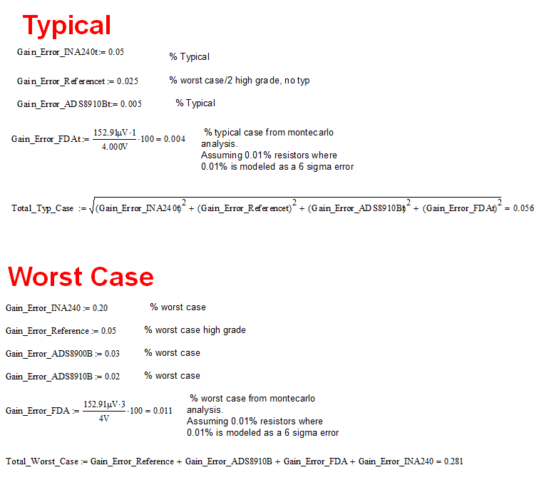
The typical total gain error of the system is calculated by performing the square root-sum-of-square (RSS) of the typical gain error specifications of the different components in the signal chain. The worst case gain error is the addition of the max gain error specifications of the devices in the signal chain. The worst case error is a very conservative estimate.
The INA240 voltage supply is VS=5.5V maximum; therefore is output is limited to +VS-0.2V; and VGND=0.10. The ADS8694 optimal scale setting would be 0V-5.12V.
The design shown on SBAA249 was able to achieve a gain error 0.056% typical (based on the RSS of typical gain error datasheet specs of the devices) and 0.281% worst case error (based on the addition of the maximum gain errors of the components) after performing a 1 point offset null calibration. Below is an example of a typical/max gain % error calculation of the design of SBAA243.
http://www.ti.com/lit/an/sbaa243/sbaa243.pdf
Thank you,
Kind Regards,
Luis Chioye
Hi Benjamin,
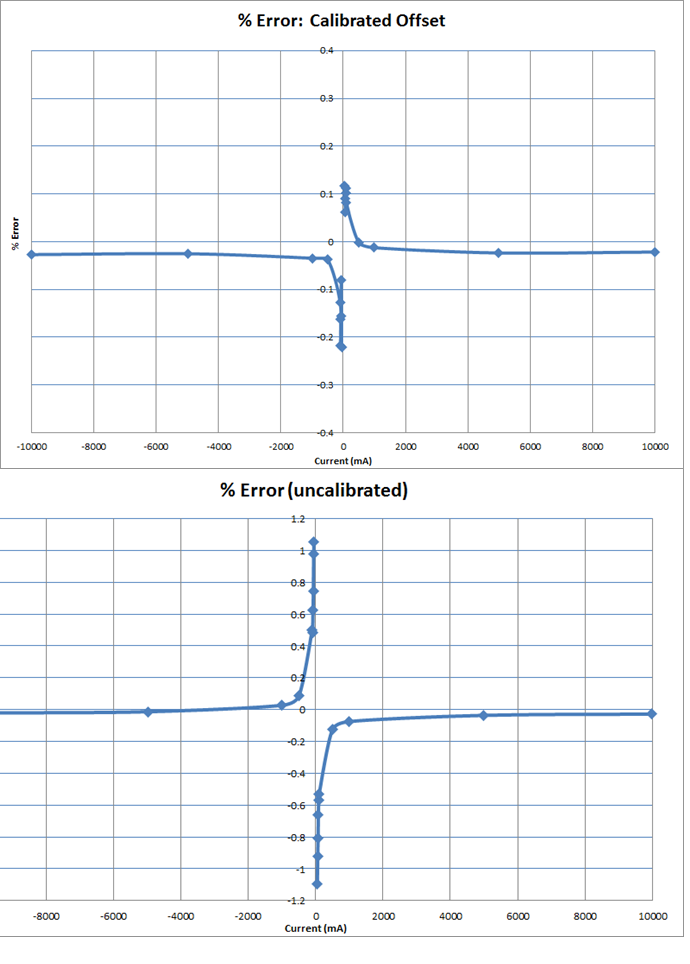
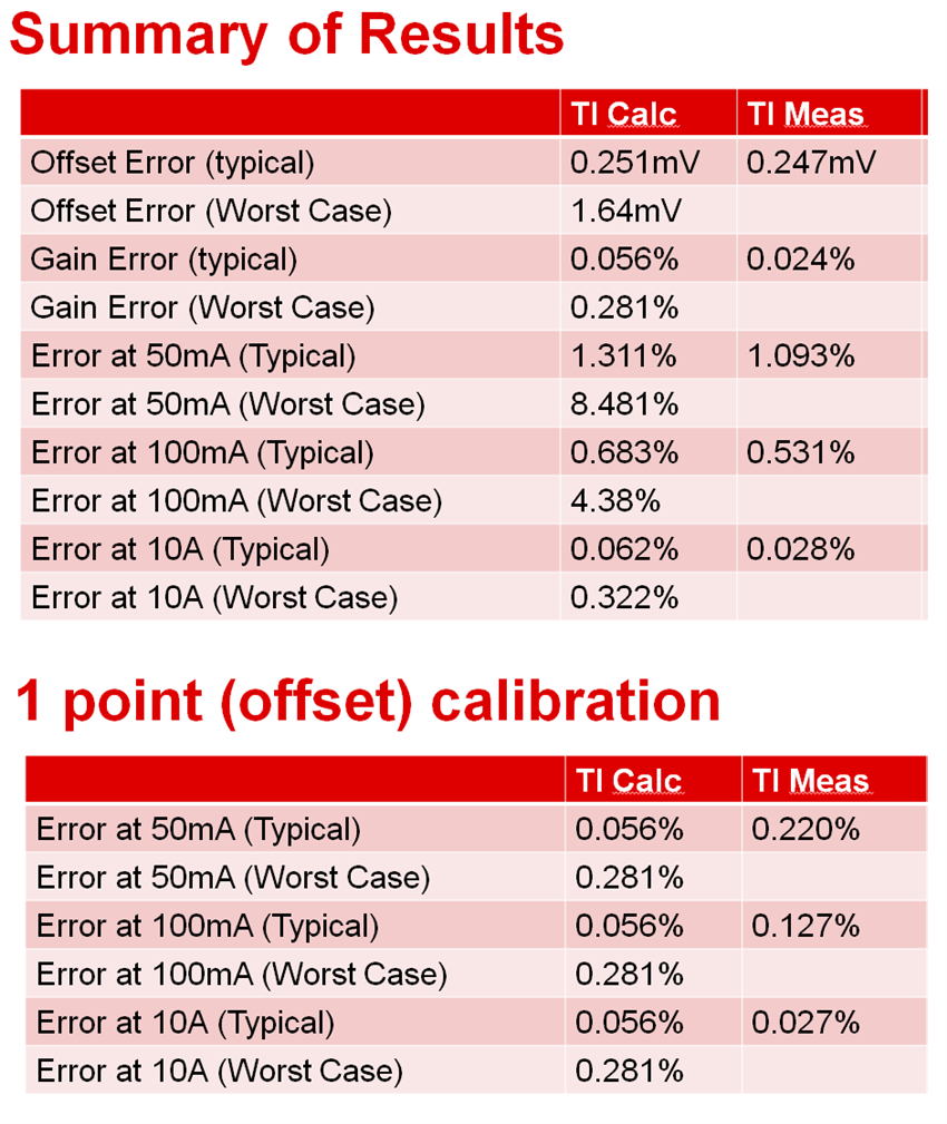
This particular design with the INA240, OPA320, THS4551 and ADS8914B had a range of 50mA-10A. The plot below provides a summary of the accuracy error (measured) for the design of SBAA243 at different current levels. Also below are two tables with the calculated and measured accuracy error at different current levels. There are two set of results, one without offset calibration and the second one performing an offset (null) one point calibration.
The accuracy error measured without calibration at minimum scale of 50mA was 1.093%; and the error after performing one point offset calibration was 0.220%.
Attached is a power point file providing a very detailed calculation/measurement accuracy summary of results at full-scale and minimum scale, as well as the noise analysis, and the improvement of results while performing averaging.
7711.Current monitor_forum - 2-14-2017m.pptx
Hope this helps.
Kind Regards,
Luis Chioye