This thread has been locked.
If you have a related question, please click the "Ask a related question" button in the top right corner. The newly created question will be automatically linked to this question.
Hello,
setup:
- 5V to 3.3V logic level shifter as depicted in "bidirectional converter" - https://jeelabs.org/book/1504d/
- Arduino UNO
- Arduino IDE 182
- TQFP to100 mil adapter PCB
- No 47 Ohm resistors; the rest identical to figure 94 of "ADS114S0xB Low-Power, Low-Noise, Highly Integrated, 6- and 12-Channel, 4-kSPS, 16-Bit, Delta-Sigma ADC With PGA and Voltage Reference" document
- SPI.beginTransaction(SPISettings (20000000, MSBFIRST, SPI_MODE1)); // 2 MHz clock
tried:
- RREG-ing 15 registers as below:
addr = B00100000; //
aux = 0; //
// data = 0xFF;
int c = 0xF;
while (c-- != 0)
{
data = SPI.transfer16((uint16_t) (addr + c << 8 | aux));
// delay(1);
data = SPI.transfer(0x00);
// data = SPI.transfer(0x00);
Serial.print("Devie ID: ");
Serial.println(data);
SPI_next_byte();
}
- RREGing from 0h and 4h
- inserting a 47 Ohm resistor close to the ADC part for the MISO line
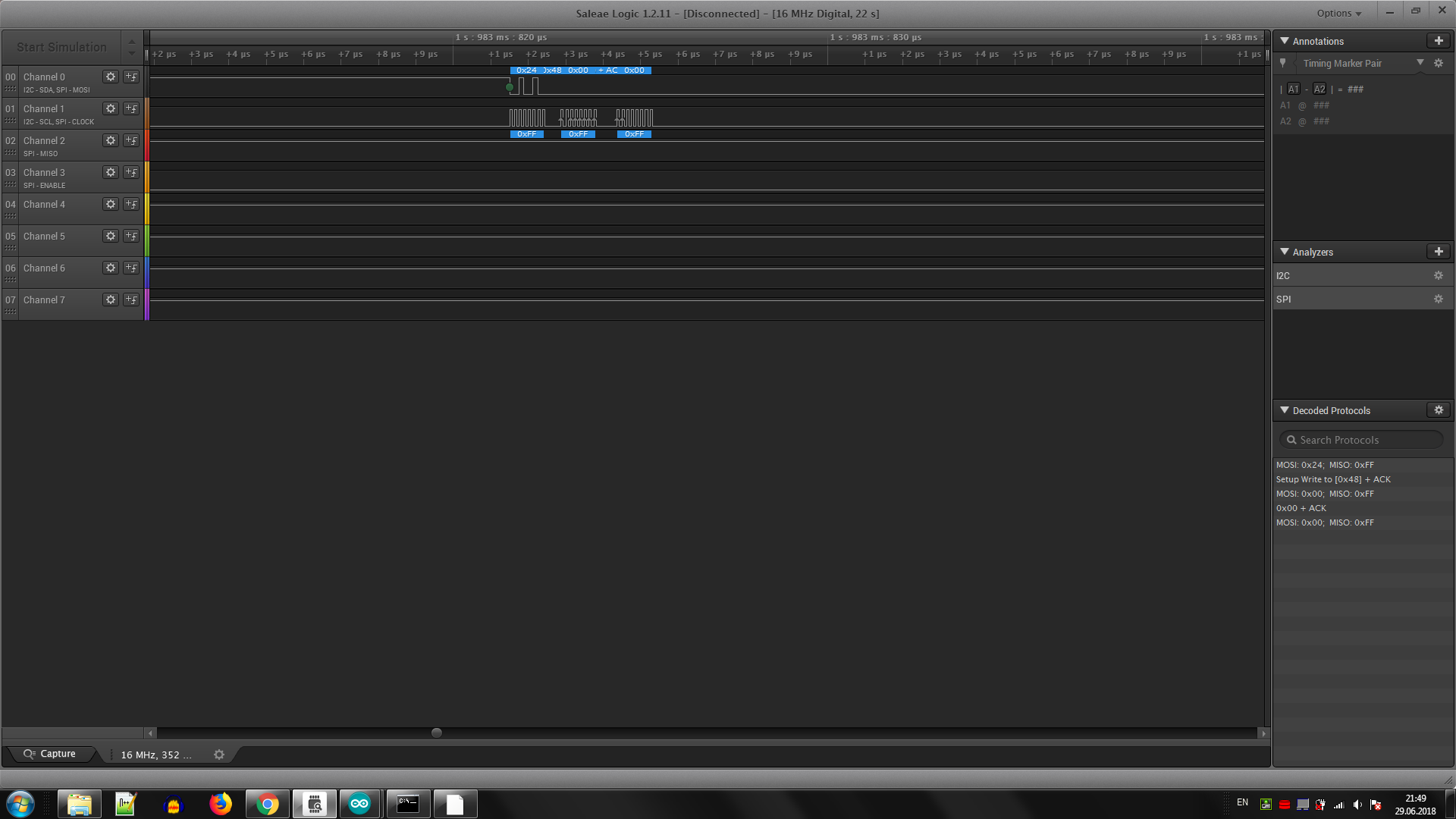
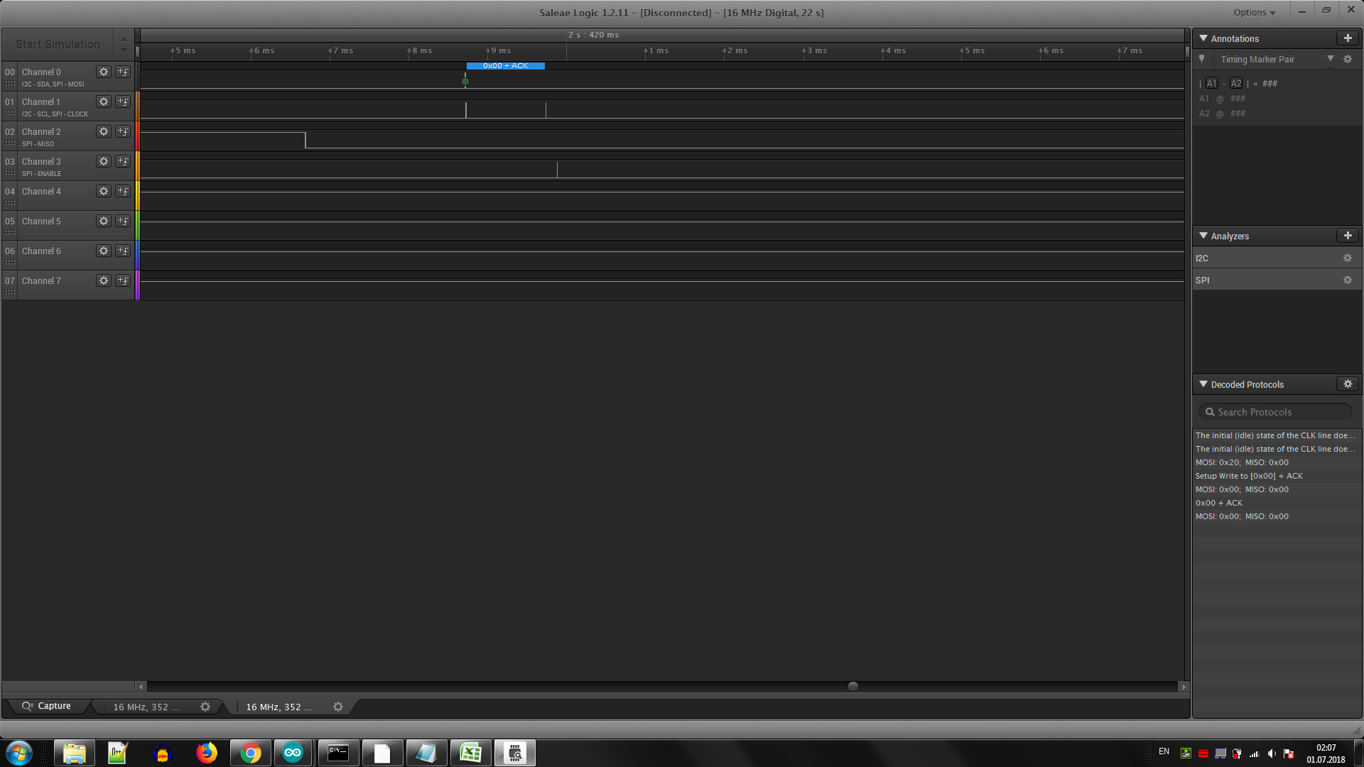
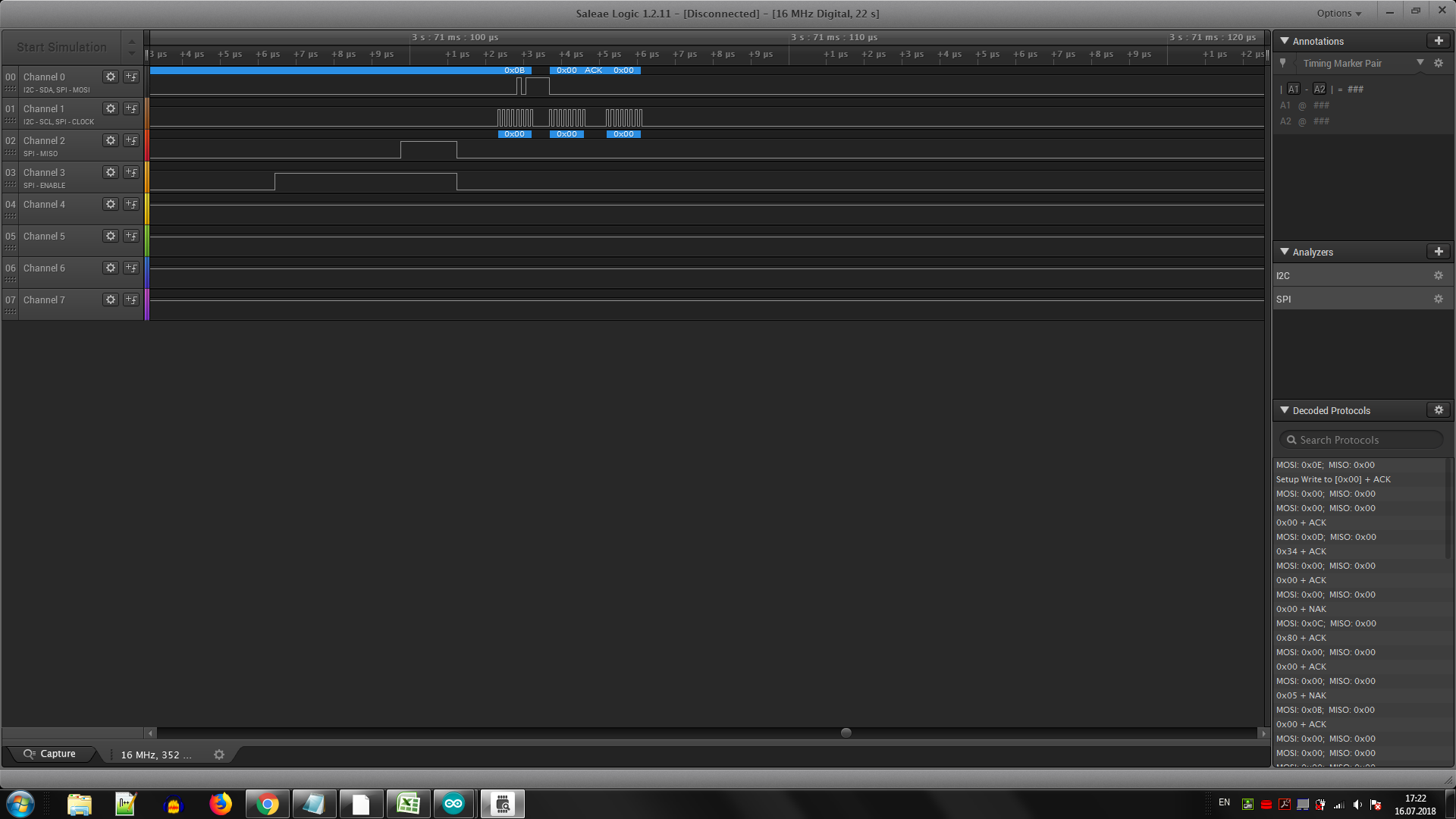
results:
- See attached
question:
- why does the SPI compatible part not yield a SPI compatible result ?
Thanks you,
Praveen
Dinesh
Yours trully
Hi Catalin,
I'm a little confused by what I see. Your MISO line changes outside of the SCLK region. Are you sure you are connected to the proper pin(s)?
You may also just want to make sure your device is out of the reset condition by setting the START pin high and checking DRDY to see if it is toggling at the default rate of 20sps (50ms period). If you do not see this happening, then the device is still held in a reset condition by either the RESET pin not truly high, or not all the supplies are present at the device.
If DRDY is toggling as expected, then you should be able to read the registers.
Best regards,
Bob B
hello Mr. Bob,
I have done some adjustments to the IOVDD supply voltage: put it to 5V from the previous 3.3V. Also tried resetting it after power up:
digitalWrite(PIN_RES, LOW); delayMicroseconds(2); digitalWrite(PIN_RES, HIGH); delay(2); // delay until our ADC resumes after a reset (max 4096 * t_clk) digitalWrite(PIN_NSEL, LOW);
And quite a few rewirings and resoldering. The thing started budging.
>>by setting the START pin high and checking DRDY to see if it is toggling at the default rate of 20sps (50ms period). If you do not see this happening
I can see that happening. Following are various voltages:
DVDD - DGND: 3.32V
IOVDD - DGND: 4.84V
AVDD - AVSS: 4.84V
!RESET - DGND: 4.83V
START/SYNC - DGND: 4.84V
CLK - DGND: 0V
REFOUT - DGND: 0V
REFCOM - DGND: 0V
DOUT/!DRDY - DGND: 3.2V when a logic analyzer probe is connected or 0.1V when not (idle SPI)
SCLK - DGND: 0V (idle SPI)
DIN - DGND: 0V (idle SPI)
Help! Thanks!