Hi, I'm a korean beginner developer, so please understand that I'm not good at using Eng.
I'm developing ECG kit for Arduino with ADS1292R for 4 wks. but I have a problem now.
The problem is that SPI communication dosen't work at all even SDATAC at first. and I don't know the reason hardware or software....
I have been double checked my Hardware twice, but there is no short circuit.
Here's how I found out that SPI communication is not working:
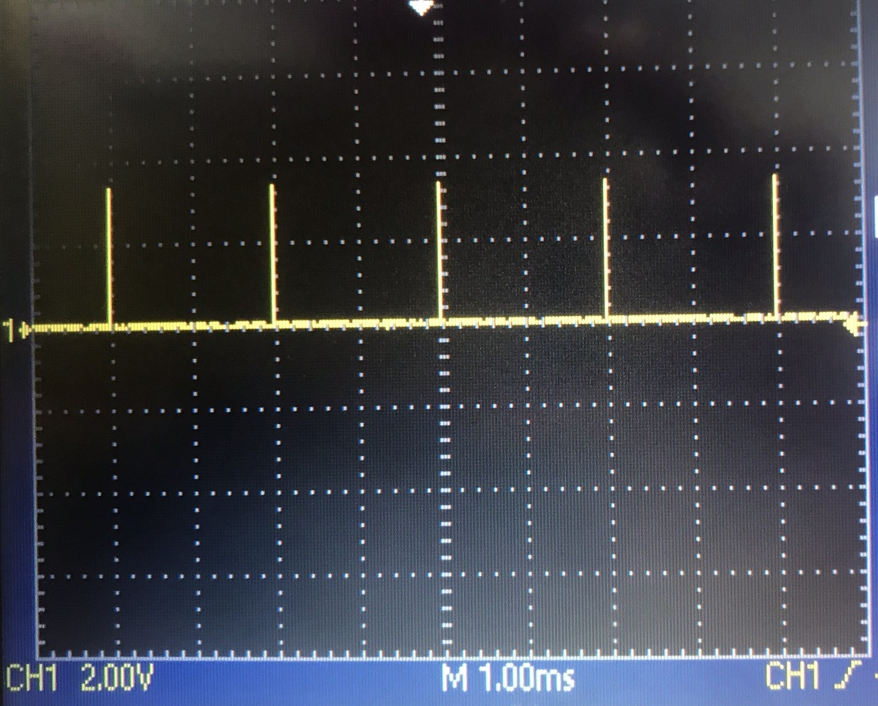
Test1.[>>> issue reset squence > toggle START pin High > check DRDY change continuously High-Low (with oscilloscope) > toggle START pin Low > issue SDATAC to stop read data continuously mode > toggle START pin High again > check DRDY stay always Low DRDY still change continuous High-Low (I guessed that DRDY stay low if Read data continuous mode was stopped by SDATAC command)]
Did anyone experience the same problem? Do you have any troubleshooting suggestions?
Can you find the cause for this on the below code, SPI configuration or schematics that I am using?
//~~~~~~~~~~~~~~~//
#include <SPI.h>
//~~skip about register and commands definition~~//
void send_Command(int cmd){
digitalWrite(PIN_CS, LOW);
delayMicroseconds(1);
SPI.transfer(cmd);
delayMicroseconds(6);
digitalWrite(PIN_CS, HIGH);
delayMicroseconds(5);
}
void init_Pins() {
pinMode(SCLK, OUTPUT);//pin13
pinMode(DIN, OUTPUT);//MOSIpin11
pinMode(DOUT, INPUT);//MISOpin12
pinMode(PIN_CS, OUTPUT);//pin10
pinMode(PIN_RESET, OUTPUT);//pin7
pinMode(PIN_START, OUTPUT);//pin8
pinMode(PIN_DRDY, INPUT);//pin9
digitalWrite(PIN_CS, HIGH);
digitalWrite(PIN_START, LOW);
delay(1);
}
void init_Serial() {
Serial.begin(9600);
Serial.flush();
delayMicroseconds(100);
}
void init_SPI() {
SPI.begin();
SPI.setDataMode(SPI_MODE1);
SPI.setClockDivider(SPI_CLOCK_DIV16);
SPI.setBitOrder(MSBFIRST);
}
void init_ads() {
digitalWrite(PIN_RESET, HIGH);
delay(1000);
digitalWrite(PIN_RESET, LOW);
delay(1000);
digitalWrite(PIN_RESET, HIGH);
delay(100);// Issue Reset Pulse
digitalWrite(PIN_CS, LOW);
delay(1000);
digitalWrite(PIN_CS, HIGH);
delay(500);// Reset communication
send_Command(SDATAC);
digitalWrite(PIN_START, HIGH);
}
void setup() {
delay(3000);
init_Pins();
init_Serial();
init_SPI();
init_ads();
}
void loop() {
}
//~~~~~~~~~~~~~~~//
and all the ADS1292R register is default (because I can't communicate by SPI at all)
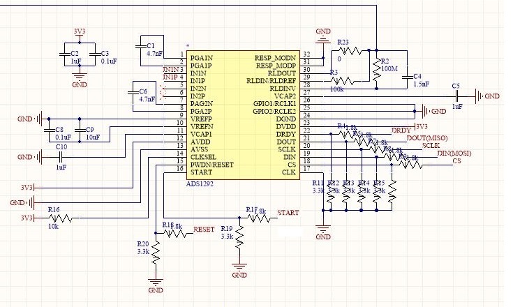
Schematic
3V3 provided from Arduino 3.3V.
1.8k:3.3k Logic converter.
I'm studying alone, so I don't have any person who can confirm my design...
even i knew that DVDD and AVDD or DGND and AGND must be separated, after order PCB...
Yellow: DIN(0x0A: SDATAC)
Blue: SCLK
CS(LOW) during transaction
DRDY
please help me....
thanks


