This thread has been locked.

If you have a related question, please click the "Ask a related question" button in the top right corner. The newly created question will be automatically linked to this question.

CCS/THS1206M-EVM: Configuration read from 'RBACK' is right, but nothing can be read when it is set to 'Test Mode'

Part Number: THS1206M-EVM
Other Parts Discussed in Thread: TMS320F28335, , THS1206

Tool/software: Code Composer Studio

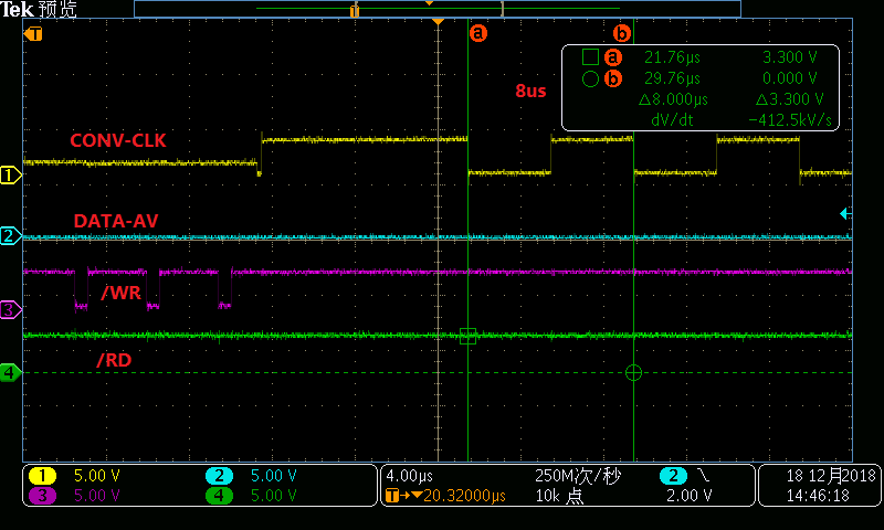
THS1206M-EVM is connected to TMS320F28335,when D0-D11 are assigned to GPIO2-GPIO13 and CS1 /CS0 /WR /RD connect to GPIO68 70 72 74 respectively. GPIO0 is set to get DATA_AVL signal and triger interrupt at rising edge.GPIO1 is set to control CONK_CLK/CONVST. We adopt internal reference REFP REFM. This is the basic connection pattern.
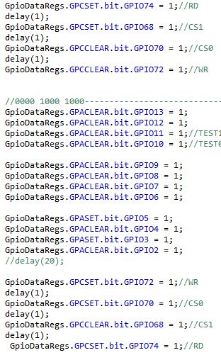
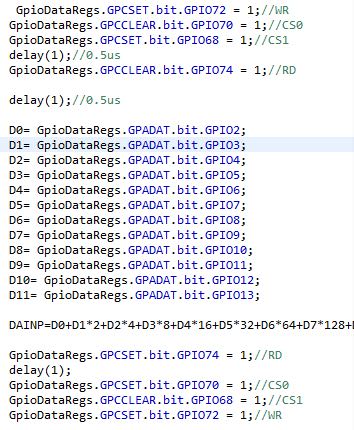
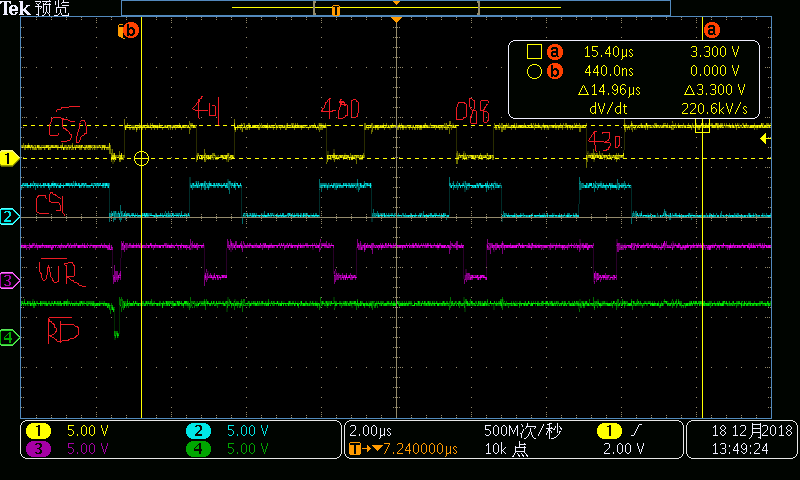
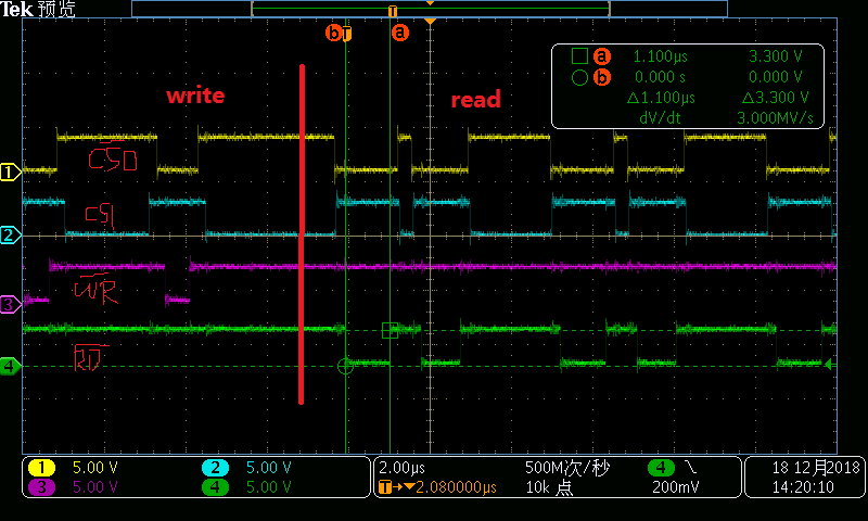
To configure CS1 /CS0 /WR /RD, we write 0x401,0x400,0x088,0x430 to D0-D11 successively. CONV_CLK signal is 10us 50%pwm. However,we can not get DATA_AVL signal. Therefore, we get to test it. First, when RBACK=1,we read two times in for circles and we get 0x088,0x430,which means the write and read option may be successful. Next,we set.TEST1、TEST0 to  01 10 11 to get in 'Test mode',but the value we read is zero which has no change. Therefore, what is wrong? why can not we get DATA_AVL signal or get in 'Test Mode'?
  • Hi There and welcome to our e2e Forum!

    Can you post a logic analyzer screen capture of your communication interface with the THS1206? You need to make sure you are accounting for the pipeline delay in the THS1206 before you attempt to read any conversion results. If you read before the trigger level is satisfied, you will not get a DATA_AV output signal. The DATA_AV output will only become active once the FIFO trigger level is satisfied (see Figures 25 through 28).
  • Dear Hendrick,

    Four figures are attached here. Fig 1,Fig 2 and Fig 3 are used to verify the 'Write' and 'Read' operation when 'Read' operation is written in For circles. Signal 1, 2, 3, 4 represent /CS0 CS1 /WR /RD respectively. Detailed information is in figures. In Fig 4, 'Read' operation is written in interrupt which takes place at the rising edge of DATA-AV. Signal 1, 2, 3, 4 represent CONV-CLK DATA-AV  /WR /RD respectively in Fig 4.

    yours sincerely

    Fig 1

    Fig.2

    Fig. 3

    Fig. 4

  • Hi!

    In Figure 4, how long did you continue the CONV-CLK? Also, in your case it would probably be best to set the DATA_AV type to '0' so that it's a static signal.