This thread has been locked.

If you have a related question, please click the "Ask a related question" button in the top right corner. The newly created question will be automatically linked to this question.

ADS8638: data invalid for first couple of reads, then OK

Part Number: ADS8638

Hi, I have noticed when using the ADS8638 that the first couple of reads of the ADC return "junk" data, after that it seems OK.

The command I am sending is 0x0810, which is a manual mode read for channel 1 (register address 4)

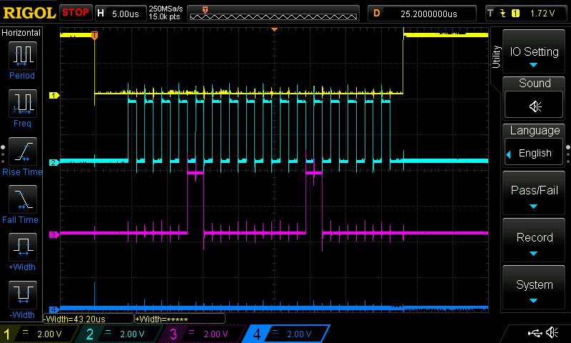
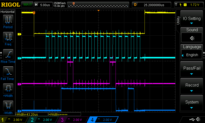
The signals look OK on the scope, please see attached.

The return data is at first zero (the bottom trace on the scope), after that the return data is sensible (return code of oxff2 which is about right for that ADC input which is connected to 5V)

The ADC is controlled from a microcontroller over the SPI bus. The microcontroller code is a continuous loop, continually sending the same command every ~ 2 seconds.

Here is the code snippet:

AdcData1 = Ads8638TxRx(ADS8368_SELECT_CHANNEL_1);
sprintf( buffer, "ADC ADDRESS = %x hex\tADC DATA = %x hex\n", (AdcData1 & 0xf000), (AdcData1 & 0x0fff) );
HAL_UART_Transmit(&huart3, (uint8_t *)buffer, strlen(buffer), 0xFFFF);

Here is the serial port debug output:

ADC ADDRESS = 0 hex ADC DATA = 0 hex

ADC ADDRESS = 0 hex ADC DATA = 0 hex

ADC ADDRESS = 1000 hex ADC DATA = ff1 hex

ADC ADDRESS = 1000 hex ADC DATA = ff2 hex

ADC ADDRESS = 1000 hex ADC DATA = ff3 hex

Any ideas of things to check please?

thanks, Nick

  • Hi Nick,
    I will look into the detail and get back to you soon, thanks.

    Best regards
    Dale
  • Hi Nick,
    I want to understand your code well before addressing the issue, I guess that the "ADC ADDRESS = 1000 hex" is the command (1000 hex) you sent to ADC on SDI, actually this is the command to program "Ch1LA MSB" register because you were writing 0x00 data to 0x08 register address, please let me know if this is the operation you wanted, thanks.

    Regards,
    Dale
  • Hi Dale,

    Thank you for your reply.

    No, the command that I send to the ADC is this :

    AdcData1 = Ads8638TxRx(ADS8368_SELECT_CHANNEL_1);

    where "ADS8368_SELECT_CHANNEL_1" is #define to be 0x810 (i.e. a command for "manual mode" selecting channel 1, register address 4)

    And the data that the ADC sends back in response to this command is, at first, just all zeros (you can see the flat oscilloscope trace, the dark blue one at the bottom). But then after a couple of "reads", the data that the ADC sends back looks OK (the address, i.e. bits15-12, are 0x1000, i.e. channel 1, and the data is 0XFF2 - this also is about correct for a 5V input signal on that channel).

    My question is, what does the ADC send back the all zeros for a couple of cycles?

    thanks, Nick

  • Hi Nick,

    Understood, thanks for explanation. Can you please confirm how many cycles you got 0 hex code (ADC ADDRESS = 0 hex ADC DATA = 0 hex)? two cycle 0 hex data are reasonable because each DIN command is executed on the next /CS falling edge, the conversion data for your selected channel will be shifted to SDO after the command is executed, please check the timing highlighted as below.

    The default channel is Channel 0 after powering on the ADC, this should be why channel 0 with 0x0xxxx was shown before you got the data of right channel, can you please connect a DC signal(not 5V) to channel 0 input when doing the same test you did? we can check if 1st and 2nd cycle data will not be zero. Thanks.

    Regards,

    Dale

  • Hi Dale,

    OK, thanks for the clarification.

    The first 2 cycles only gave a code of 0 hex. After that, it was fine.

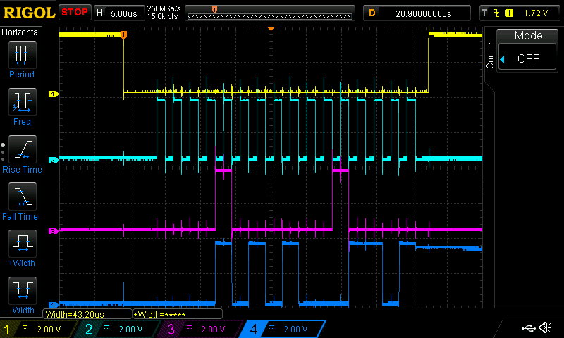
    I connected a DC level to channel 0, and those first 2 reads now contain what looks like valid data for that channel input.

    See scope trace and debug output below.

    thanks, Nick

    ADC ADDRESS = 0 hex ADC DATA = a8e hex

    ADC ADDRESS = 0 hex ADC DATA = a8c hex

    ADC ADDRESS = 1000 hex ADC DATA = ff2 hex

    ADC ADDRESS = 1000 hex ADC DATA = ff2 hex

    ADC ADDRESS = 1000 hex ADC DATA = ff1 hex

    ..........

  • I forgot to ask - is the default channel sequencing mode at power up "auto" or "manual"?

    And if we are in "manual" mode, based on what you have written above, am I correct in thinking that if we want to change from one channel to another, then we need to perform 2 cycles until we get the correct data?

    thanks, Nick
  • Hi Nick,

    The default mode is Manual mode and default channel is Channel 0 after ADC device powers up, please refer to the flowchart in Figure 93. The test you did also verified that the first two data come from Channel 0. Hence, all the data you got are correct, and your ADS8638 works well.

    Thanks&regards

    Dale

  • Hi Dale,

    The one question remains from my previous post:

    "am I correct in thinking that if we want to change from one channel to another, then we need to perform 2 cycles until we get the correct data?"

    Lets suppose we have some psuedo code that looks like this:

    SEND_COMMAND_TO_SELECT_CHANNEL_1

    SEND_COMMAND_TO_SELECT_CHANNEL_3

    SEND_COMMAND_TO_SELECT_CHANNEL_5 << WE GET CHANNEL 1 DATA HERE

    SEND_COMMAND_TO_SELECT_CHANNEL_7 << WE GET CHANNEL 3 DATA HERE

    Based on what you have said before, I believe that there is a 2 cycle delay between sending a command to change to a different channel, and the actual conversion data for that channel being available.

    Is this correct please?

    So, our pseudo code might be rewritten to look like this:


    SEND_COMMAND_TO_SELECT_CHANNEL_1

    <DUMMY SPI CYCLE 16 SCLKS>

    <DUMMY SPI CYCLE 16 SCLKS>

    READ_DATA_FOR_CHANNEL_1


    thanks, Nick


  • Hi Nick,

    Please check the timing graph I highlighted above, your understanding is correct.

    You can use DUMMY command but it will reduce your maximum sampling rate, actually it isn't necessary because you have known the conversion data's position for each channel so your software can process these data directly or adjust them if you want.

    Regards,

    Dale

  • Thanks Dale

    I now understand the latency involved with using this converter.

    I think the datasheet could make this clearer though (it makes it clear for transitioning between manual <> auto mode, but even when you just change channels in manual mode, the same latency exists.)

    regards, Nick