This thread has been locked.

If you have a related question, please click the "Ask a related question" button in the top right corner. The newly created question will be automatically linked to this question.

DAC38RF89: Start-up Sequence Problem

Part Number: DAC38RF89
Other Parts Discussed in Thread: DAC38RF82, LMK04816,

Hi!

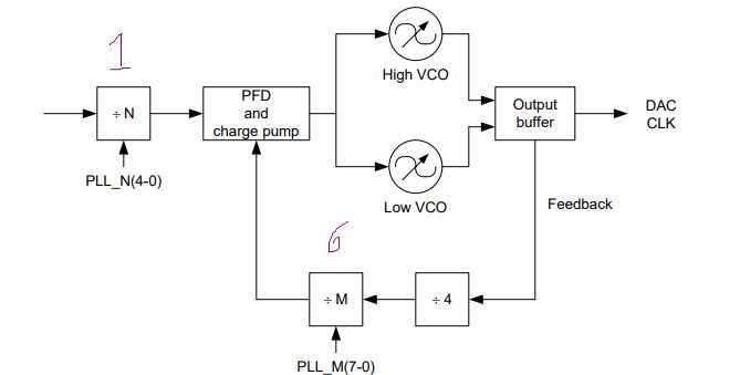
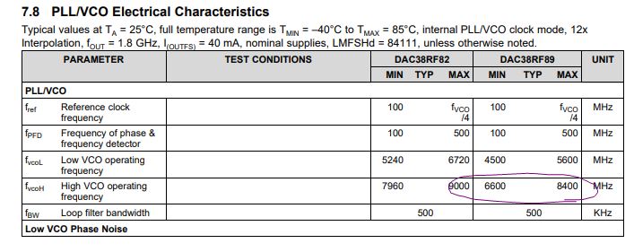
I am using the DAC38RF89. DACCLK frequency is 328 MHz, DAC clock frequency is 7872 MHz.

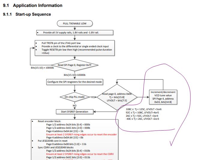
There is a problem when I 'm trying to implement Figure 141 (refer to DAC38RF82 datasheet, p.126):

On "Chip PLL Mode" stage, readed data from <page 0, address 0x06> always the same and never change - 0xc002.

When configuring DAC power consamption increases about 1 W. 

Can you give me an advice?

Thanks. 

  • Hi Andrey,

    I recommend that you adjust the VCO code to re-center the VCO to the frequency that you need at 7872MHz. The VCO code is used to compensate for the part-to-part variations due to process/voltage/temperature. It is unique for each chip, so you will need to follow the part of the flow chart to adjust for it

    I would also recommend that you check the N and M dividers such that the PLL is setup to have proper feedback loop to be lock. The N and M divider may need to be programmed as N-1 or M-1. You will need to check the datasheet for detail

    Regarding the VCO code adjustment, you may need to program towards the lower range of the total range since 7872 is closer to the lower range rather than the upper range

    Lastly, i recommend that you dump your register settings into the format that the DAC38RF8x EVM GUI can accept. We can load it into the GUI and check the overall setting to see if we are missing anything.

    -Kang

  • Hi Kang

    Thanks fo reply.

    I will describe my steps:

    1. Turn on the power.

    2. Load config data into the CDS (lmk04816) and wait for PLL lock.

    3. Set TXENABLE  to '0', then forming reset pulse 50 us duration.

    4. Check reg 0x07F, bits [15:10] for state 10000b.

    5. Load config data into the dac38rf89.

    6. Read reg 0x006 for check temperature (reg 0x006, bits[15:8]) and LFVOLT (reg 0x006, bits[7:5]): readed value is 0xC0E2 (temp is -64 degree celsius, LFVOLT is 7). This value has changed from 0xC002 to 0xC0E2 after loading new cfg file for dac38rf89.

    7. Write to reg 0x433, bits[14:8] vaues from 1 to 127 does not change LFVOLT parameter, but increase power comsumption aproximetly 0.7 W.

    8. Write to reg 0x005 bit [0] value '0', then read this reg, bit[0] and got value '1'.

    Config file in attachment.my_dac38rf89.cfg

  • Andrey,

    You are operating in a quite cold environment. at -62 degree die sensor temp. Please try to bring-up to room temp to see if you can see any different result.

    I have briefly checked your PLL programming and the setting appears to be correct. I will have to defer to my colleague who is more familiar with the product to look into this further

    You may also measure the ATEST pin on the chip, and do the following programming to check the internal net voltage via the ATEST pin.

  • Kang, 

    I work with DAC in the room. DAC temperature is constant right after switching on and after an hour of work. The temperature never changes, no matter when I read the temperature immediately after resetting the DAC before or after tuning. Temperature FPGA on same printboard at this time 40-45 degrees. 

    Tried to change the PLL_VCO from 1 to 127 (increment  1), but neither the LFVOLT (still 7) nor the temperature (still -64) has changed.

  • Andrey,

    Fundamentally, I think you will need to confirm the SPI read and write sequence is correct. There are fixed DIE ID registers on the chip. Please try to read back these registers to ensure good SPI transaction before proceeding

  • Kang,

    I'm checked write/read reg via SPI, I shink that SPI read and write sequence is correct.

    From reg 0x07F i read 0x8009 when SLEEP pin is 0 and 0x0009 when sleep pin is 1.

    If i'm write bit[15] reg 0x000, then i can see that SPI regs set to default. If write in the bit[7] reg 0x001 theh SPI set in the 4bit mode.