This thread has been locked.

If you have a related question, please click the "Ask a related question" button in the top right corner. The newly created question will be automatically linked to this question.

ADS1247EVM: Where am I doing wrong with ADS1247?

Part Number: ADS1247EVM

I need to measure temperature using a custom RTD made out of a thin film of gold deposited on a glass substrate, with a 25°C resistance of about 40 Ohm and I decided to use an ADS1247 due to its versatility.

In order to become familiar with the IC, I bought the official TI evaluation module (ADS1247EVM) and I prepared a test circuit where I'm trying to make a ratiometric measuerement of a fixed precision resistor of 1 kOhm, in series with another identical one.
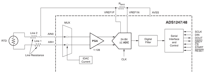
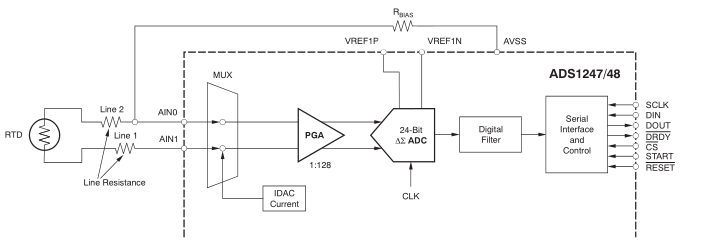
The serie is powered by 1 mA IDAC current and the second resistor is used as Rbias and connected to the reference inputs in order to provide the reference voltage to the ADC.
The scheme is exactely the one reported in this picture, got from the SBAA180B application note from TI.


What I'm expectiong is to get a full-scale measurement, what I'm obtsining is a completely non-sense value, oscillating in the full range of measurement.
I tryied to do the same ratiometric measurement using the internal reference and disconnecting the Rbias from the Vref inputs (this is not clear from the datasheet but it appears necessary in my opinion) but what I get is the same.
The device seems to work properly, I followed the pseudo-code example from the ADS1247 datasheet and reading the registers after having wrote them gives the expected values, I performed also some test measurements and the quantities like the internal Vref or the IDAC current are the expected ones. Moreover, disconnecting the AN inputs during the conversion, you get a low value (like the hex CC), compatible with the noise, I guess.

So, where I'm doing wrong?
Thank you in advance for every hint!

  • Hi Filippo,

    Can you tell us exactly how you have connected the resistors to the ADS1247EVM and the values you have written to the configuration registers? Are you using the ADCPro software?

    The IDAC current requires that you have a complete path to AGND, so if you try to use the internal reference and disconnect the RBIAS, then you disconnect the path to ground.

    Best regards,
    Bob B
  • Hi Bob,
    thank you for your reply.

    I'm not using the ADCPro software, I'm using the ADS1247EVM standalone with a microcontroller.

    Of course I've connected the resistors series to the AGND, I'll report here a more detailed explanation of my setup.

    1) Two 1 kOhm resistors in series, one used as Rbias for external Vref, connected to the REF pins and to AVSS (AVSS shorted with REF-). AVSS shorted with AGND from the J10 connector bridges (AGND appears to be shorted also with DGND and with the generic GND of the board), the switch on the board is set on the right position (EXT).
    The second resistor take the place of the RTD and it's connected to AN0 and AN1.
    This is substantially the configuration for a 2-wire ratiometric measurement reported on the SBAA180B application note.

    I set the registers in order to drive the resistors with a current of 1000 uA, from the AN1 pin (and I checked it measuring the voltage drop on Rbias, which was 1 V as expected). The internal reference Vref is set to be always ON as specified in the ADS1247 datasheet, REFP0 and REFN0 selected for external voltage reference. PGA gain and acquistion rate have been left as from the default settings after device reset. Here the binary value of registers that I wrote:

    MUX0: 0b00000001
    MUX1: 0b00100000
    IDAC0: 0b00000110
    IDAC1: 0b00011111

    My expectation from this configuration is to read a full scale value, I read instead a completely random value.

    2) Two 1 kOhm resistors in series, the first no more connected to the REF pins but connected to the board GN (shorted again with AGND, DGND and AVSS), the switch on the board is still set on the right position (EXT), maybe this is wrong.
    The second resistor as before, this configuration differs from the previous one only for the connection of the base resistor to the REF pins.

    I set the registers again in order to drive the resistors with a current of 1000 uA, from the AN1 pin, the internal reference Vref always ON and connected to REFP0 and REFN0 pins (testing the voltage here you get the expected value of 2,048 V).
    Here the binary value of registers I wrote:

    MUX0: 0b00000001
    MUX1: 0b00111000
    IDAC0: 0b00000110
    IDAC1: 0b00011111

    My expecttion from this configuration is to read a mid scale value, I read instead a completely randum value again.

    Of course I've checked the voltage supply provided th the board, they are OK.

  • Hi Filippo,

    The process appears to be ok, although consider that the resistors need to be well matched to get a full-scale reading for test 1.

    Have you verified your communication? Is the START pin high? Are you reading data direct or are you using the RDATA command? The default data rate is slow (5sps) which is one conversion every 200ms. If you are using the read data directly, you need to be careful that you are not attempting to read data during the update period. I would suggest using the RDATA command and issuing the SDATAC command to halt all automatic updates to the output buffer when conversion is complete. A completed conversion is signaled by the high to low transition on DRDY.

    Can you send me the actual raw data you are getting back? Also send me scope/logic analyzer shots of the reading of the conversion results (CS, SCLK, DIN, DOUT) for both test methods.

    Best regards,
    Bob B
  • Hi Bob,

    finally I solved the issue, it was due to a cold soldering on the circuit that I used.

    Obviously I'm using the ADS1247 following your recommendations regarding the DRDY pin and avoiding a continuos reading of data. The device work very fine.

    I've produced a library to manage this device, do you think that I can put it somewhere in order to let it to be accessible for other people?

    Thank you a lot :)

  • Hi Filippo,

    Glad to hear you found your issue.  I'm not aware of any TI site where you can share your code, but there are many other places that are designed to do just that such as github.

    Best regards,

    Bob B