This thread has been locked.

If you have a related question, please click the "Ask a related question" button in the top right corner. The newly created question will be automatically linked to this question.

ADC128S052: ADC128S052 result bit?

Part Number: ADC128S052

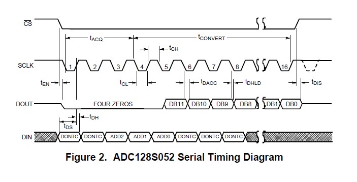
In ADC128S052 test, we found that the ADC result was 11 bits, and the datesheet did write 12 bits. Is it correct?

  • Hello,

    This device is indeed a 12 bit device.

    Would you share your test set up, to help debug why only 11 bits are being outputted?

    The most common issue is usually timing, this device needs 16 clocks to complete a conversion cycle. the first four bits are leading 0, followed by the MSB conversion result.

    Regards

    Cynthia

  • U310 is powered by 3.3V. And when the IC is selected and I put 3.3V voltage on IN0, I get 2047 from SPI. Is there any configuration issue in my program?

  • Hello,

    I believe you tried to add attachments to the post, unfortunately they were not added. Please try again, you can use the insert media option.

    Can you try using the DC input less than 1.5V, I would like to see if you are missing the MSB. If you consistently see a measurement of half the input value, then you are missing the MSB.

    Regards

    Cynthia

  • I tried to input 1V before, But the conversion result was only 0.5v, So there should be no problem of losing MSB

  • Actually, if you consistently see a measurement of half the input value, then you are missing the MSB.

    Please check your timing for when you begin to interpret the SDO data. Remember that there are four leading zeros, then the SDO data is outputted.

    An oscilloscope shot will help to visually see the digital communications. This will also help to verify if the SDO data is being outputed correctly and misinterpret through firmware.  Please share an oscilloscope shot connected to the digital lines with two frames visible

    Regards,

    Cynthia