This thread has been locked.

If you have a related question, please click the "Ask a related question" button in the top right corner. The newly created question will be automatically linked to this question.

ADS1232: ADS1232 offset failure during power on

Part Number: ADS1232

Hello,

we have a big problem with the use of the ADS1232. During the development, everything seemed to be going fine. Now we started with the zero series of 2000PCBs. And we were running into a Problem. Nearly 20% of the PCBs seems to have a Problem with the ADS1232.
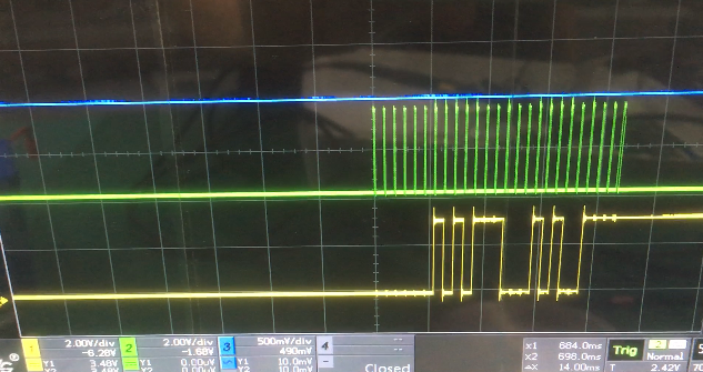
After power on, the ADS1232 sometimes generates an additional Offset. This Offset will stay until we shut down the device completely. For one Device we recoginzed three different Outputs for the same Input Signal (Load). The following three figures Shows the Signal DOUT for a unloaded scale. The only differentc is, set the scale was disconnect from power inbetween.
 
Do you have any ideas what may cause this failure?
I would be very happy about a quick response, because we are curretly running out of time in this project.   
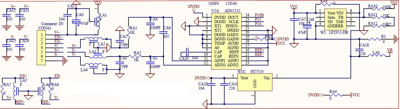
To simplify the troubleshooting, I have attached the schematic of the analog part:
  • Hi Uwe,

    Welcome to the E2E forum!  One possible issue with startup is related to the state of the PDWN pin.  We are in the process of updating the ADS1232 datasheet with additional information.  The current datasheet discusses the Power-up Sequence and timing with respect to PDWN pin going high.  The information is on page 23.  There is a requirement that PDWN must be held low for at least 10us after both AVDD and DVDD have reached nominal operating voltage.

    It appears that you can control the PDWN based on the schematic.  On power-up I would suggest holding this pin low, bring it high, then pulse (minimum of 26us low time) the power-down pin which will reset the device to a valid operating condition.  This is the information that will be added along with some suggested timing.  It is possible that what you are actually seeing is an issue where the device is improperly starting causing an error in the conversion result.  Most of the time this is seen when power is cycled off and back on, but can also occur on initial startup.

    Following the PDWN pulse, you should issue the offset calibration.  This is accomplished by sending a minimum of 26 SCLKs to the ADS1232.

    Here is a suggested startup timing:

    • Wait at least 10us after AVDD/DVDD have reached nominal operating voltage then bring PDWN high
    • Wait 100us and bring PDWN low
    • Wait 50us and bring PDWN high
    • Wait until conversion completes by monitoring DRDY/DOUT for high to low transition
    • Read conversion results and send additional SCLKs to initiate offset calibration

    Best regards,

    Bob B