This thread has been locked.

If you have a related question, please click the "Ask a related question" button in the top right corner. The newly created question will be automatically linked to this question.

ADS1232: ADS1232

Part Number: ADS1232
Other Parts Discussed in Thread: , ADS1235

Hi everyone, 

Currently, i'm designing an industrial weith scale with a maximun weight of 15 tons (6 load cells of 3 tons each connected in parallel). The main requeriments are a resolution of 50 kg approx. (easy for 24 bit resolution) and thermal stability.

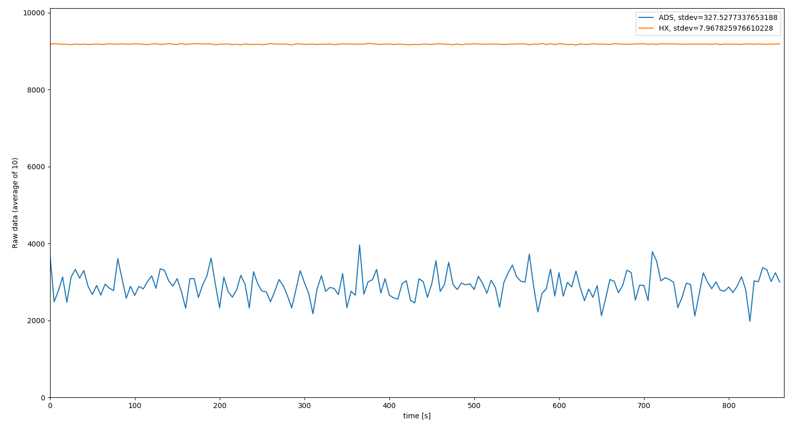
I have been testing the ADS1232, but my prior results are really bad, with a high noise level (compared to the results of the HX711). In my previous configuration i didn't consider filters for the analog signal. 

My question is, is the ADS1232 a good choice for this application, considering the thermal stability? Are analog filters critical for the application considering that the HX doesn't use it?  

As i can see in the diagrams of the ADS1232REF user's guide, are filters used for digital signals, is it necesary? 

Thanks you! 


  • Hi Tomas,

    Welcome to the E2E forum! Actually the ADS1232 noise of the ADC is actually about 1/2 the noise of the HX711, so you shouldn't be seeing higher noise.  It is good practice to have at least an antialiasing filter and in fact the HX711 datasheet does show an analog low pass filter using 100 Ohm input resistors and 100nF differential cap.  Most noise occurs on the cabling, so no matter which device you use it is a good idea to use shielded cable and properly terminate the shield to earth ground.

    The ADS1232REF shows a complete design.  You will notice that there are placeholders for analog filters.  There is added filtering for EMI/RFI on the digital signal lines.  These digital line filters are not required, but can help with external noise and transients.

    You are stating that you are seeing a lot of variation.  Can you send me your schematic of how you have the ADS1232 connected, the supply voltages being used, the data rate that you have selected, and the actual data you are seeing in codes (set of successive measurements with no load)?  It would also be helpful to know the sensitivity of the load cells you are using in mV/V and the excitation voltage.

    The HX711 is similar to the ADS1232 in a number of ways, but care must be taken that you are making a ratiometric measurement and that the ADS1232 is properly configured.  You will see the lowest noise with the SPEED pin set to 0 (10sps) and the gain set to 128 (GAIN0 and GAIN1 set to logic high).  The best dynamic range will take place at 5V analog supply.  The excitation source should also be set to 5V with the same voltage source used as the reference source. 

    If the sensitivity of the load cell is 2mV/V, then you should be able to get a resolution well below 1kg using the ADS1232.

    If you need a slightly better performing device you could consider the ADS1235.  Using 2 of these devices you could measure 6 load cells at higher data rates at the expense of higher noise (using the internal mux).  The ADS1235 would have slightly better thermal drift performance over the ADS1232 as well.

    Best regards,

    Bob B

  • Hi Bob, thanks for your reply!
    The previous experiment with both integrated circuits was performed in a perforated prototyping PCB, which explains, in part, the noisy results. Forget completely the filters in the HX module, so the comparison is very unfair, adding that the HX has its own regulator (the scheme and graphics are below).
    The sensitivity of the load cell is 3 mV / V, the excitation voltage is 5V (same source for each component), SPEED = 10 sps, GAIN = 128. To make a fair comparison, I will add filters and a separate source of excitation voltage for ADS and I will comment on the results. Another point to note (which I forgot in the original question) is that the recommended excitation voltage for the load cell is 12 V, but I could not find an ADC that would allow me to excite it with a voltage greater than 6 V.  Again, thanks for the reply!
  • Hi Tomas,

    For the ADS1232, the CLKIN and TEMP pins should be tied to GND.  If these pins float there could be erratic behavior of the ADS1232.  A differential cap between AINP1 and AINN1 is very important.  Adding additional resistance to the input will help define a specific filter cutoff frequency.

    As far as the load cell, I haven't seen one yet that requires 10 or 12 Volts even though it is recommended.  The higher voltage would help overcome some noise, but you would need to use a bipolar supply voltage for excitation to keep the input within the proper common-mode range of the ADC.  This supply arrangement would also prevent you from having a ratiometric measurement and any drift of either the reference source or the excitation source would become a part of the measurement.  The value of a ratiometric measurement, where the reference and excitation supply come from the same source, is noise of the source and any drift of the source will cancel our of the measurement.

    Best regards,

    Bob B