Hello,
I have an external 12 bit ADC (ADS7886) on a custom designed PCB with SMT32F767. This ADC interfaces with the microprocessor with SPI. Now my problem is that I couldn't read digitized values correctly. Maybe because of the incorrect driving of the ADC or setting of SPI. Based on the ADC datasheet, I should set ADC SCK as 20 MHz, but I couldn't do that with the SPI. Because I can set only either 13.5 Mbits/s or 26 Mbits/s baudrate with the SPI (with more than 1Mbits/s clock setting, the clock signal is distorting like not exact square shapes). So how can I correctly drive ADC and read the digitized values?
Thank you
This main code:
void ADC_Conversion_of_Voltage_Transients()
{

		HAL_GPIO_WritePin(ADC_CS_GPIO_Port, ADC_CS_Pin, GPIO_PIN_RESET);
		HAL_SPI_Receive(&hspi4,ADC_Buf,2,100);
		HAL_GPIO_WritePin(ADC_CS_GPIO_Port, ADC_CS_Pin, GPIO_PIN_SET);
		Sample = (((uint16_t) ADC_Buf[1]) << 8 | ADC_Buf[0]);
		//Sample = 0x0 << 12 | ADC_Buf;
		volt = (float)(Sample * (5.0 / 4096.0)); //
		testdata_in[i++]=volt;
		i %= 16;

}


SPI settings:
/* SPI4 init function */
static void MX_SPI4_Init(void)
{
/* SPI4 parameter configuration*/
hspi4.Instance = SPI4;
hspi4.Init.Mode = SPI_MODE_MASTER;
hspi4.Init.Direction = SPI_DIRECTION_2LINES;
hspi4.Init.DataSize = SPI_DATASIZE_16BIT;
hspi4.Init.CLKPolarity = SPI_POLARITY_HIGH;
hspi4.Init.CLKPhase = SPI_PHASE_2EDGE;
hspi4.Init.NSS = SPI_NSS_SOFT;
hspi4.Init.BaudRatePrescaler = SPI_BAUDRATEPRESCALER_4;
hspi4.Init.FirstBit = SPI_FIRSTBIT_MSB;
hspi4.Init.TIMode = SPI_TIMODE_DISABLE;
hspi4.Init.CRCCalculation = SPI_CRCCALCULATION_DISABLE;
hspi4.Init.CRCPolynomial = 7;
hspi4.Init.CRCLength = SPI_CRC_LENGTH_DATASIZE;
hspi4.Init.NSSPMode = SPI_NSS_PULSE_DISABLE;
if (HAL_SPI_Init(&hspi4) != HAL_OK)
{
_Error_Handler(__FILE__, __LINE__);
}
}
I have attached the results with figures:
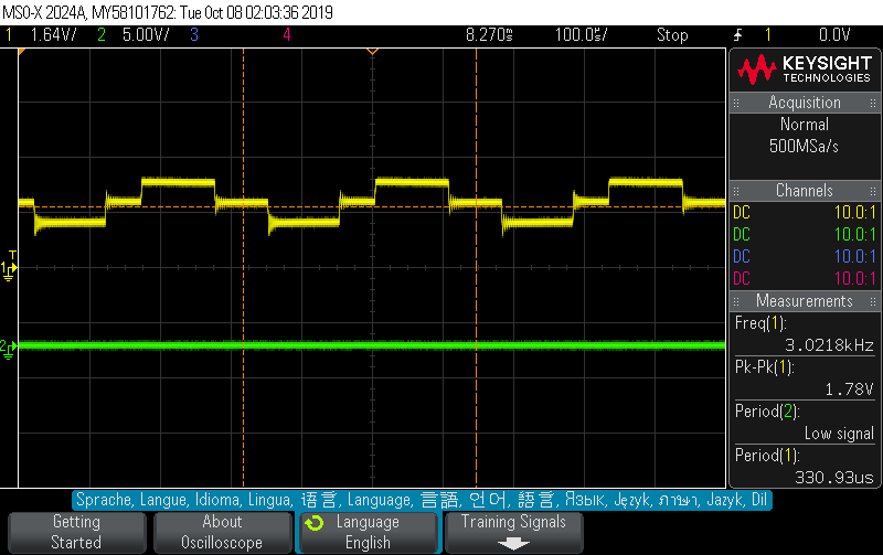
ADC input analog signal with yellow biphasic square waves.

ADC SCK signal with yellow plot and ADC CS signal with green plot.
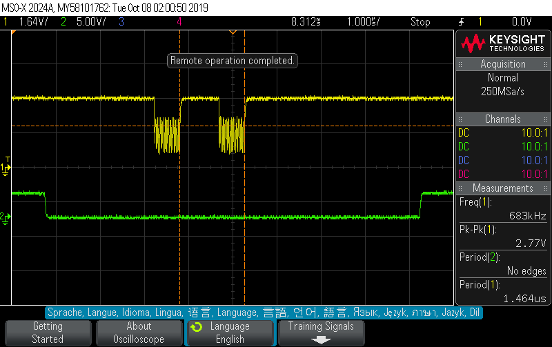
ADC SCK signal with yellow plot and ADC SDO signal with green plot.

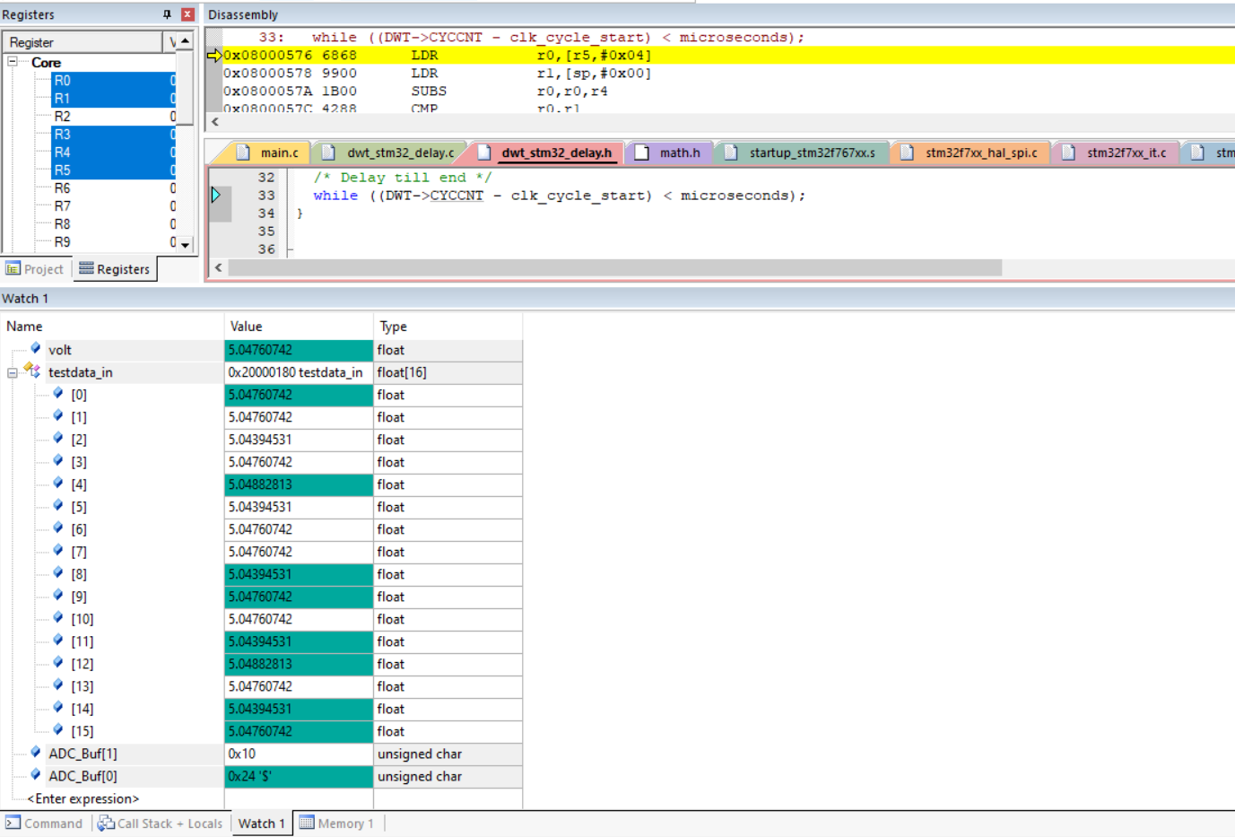
During debugging mode of the KEIL IDE, what the variables gets their values.