This thread has been locked.

If you have a related question, please click the "Ask a related question" button in the top right corner. The newly created question will be automatically linked to this question.

Compiler/ADS1198ECGFE-PDK: Device malfunction

Part Number: ADS1198ECGFE-PDK
Other Parts Discussed in Thread: ADS1198

Tool/software: TI C/C++ Compiler

Hi, 

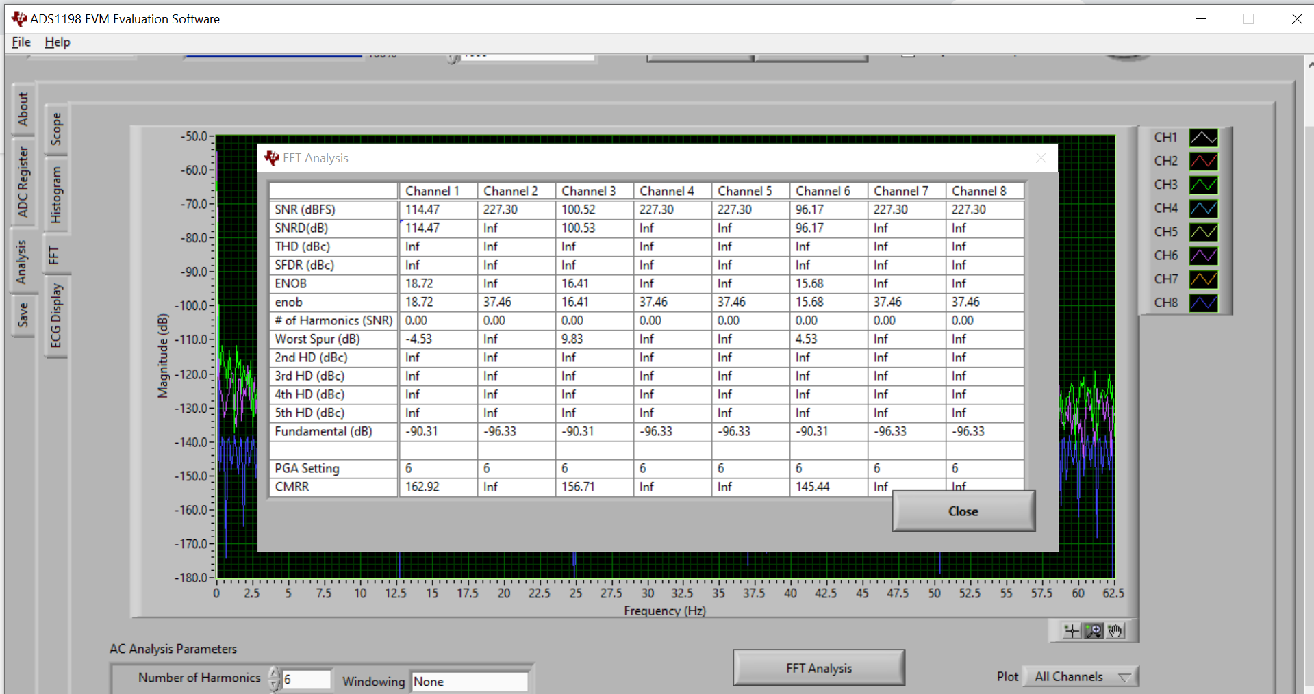
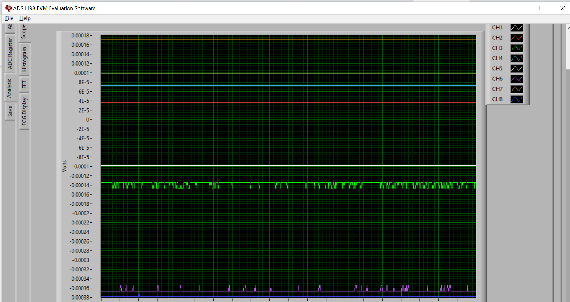
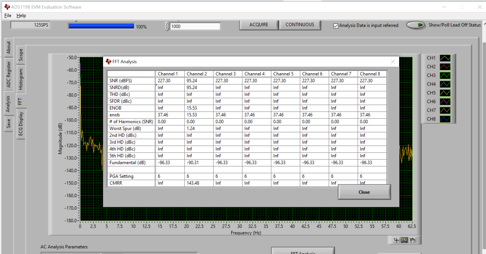
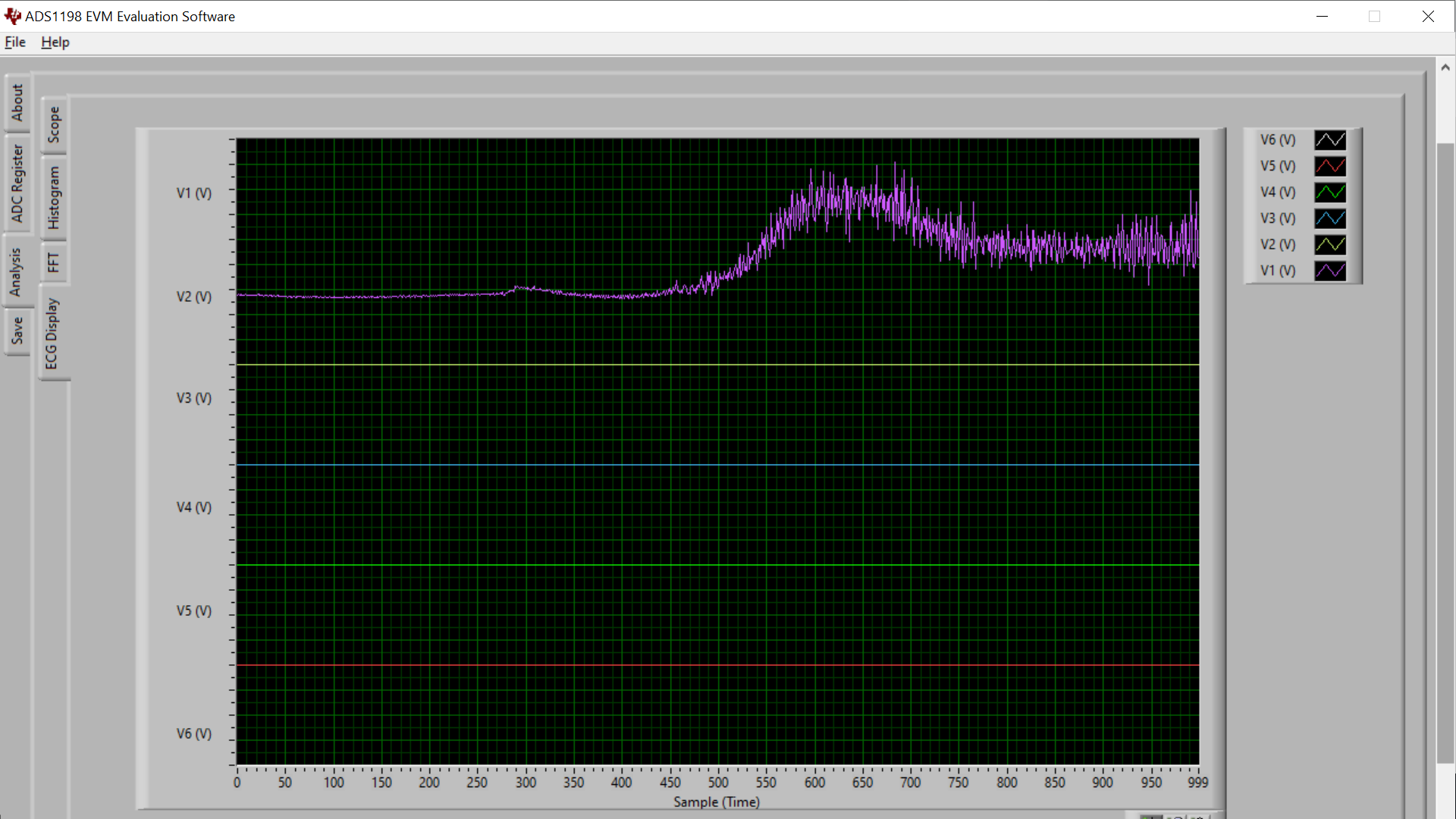
Firstly thanks for taking the time to read my post. I had just bought the ADS198ECH-FE EVA kit and had successfully gotten some good EMG results. However currently, I am getting a lot of random noises in my waveforms. I tried resetting the software settings and acquiring data with all the inputs shorted. I was supposed to get signals in a straight line with no waveforms but instead got the signal below, which shows a lot of random noises. Furthermore, the FFT analysis seems to show that the CMRR is infinite for some channels, which is really wrong. I suspect there is a malfunction on my device. Can you please help me check what the problem may be? Thanks once again.

  :

  • Hello Austin,

    Thank you for your post and welcome to our forum!

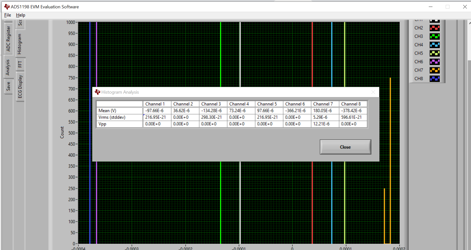
    Any analog signal chain will exhibit some amount of random thermal noise, even with the inputs to the system shorted together. What you are observing is mostly due to the thermal noise of the passive components in the input signal path as well as the ADS1198 itself. This noise should mostly follow a Gaussian distribution if you look at the Histogram analysis tab. You can learn more about this in our TI Precision Labs - ADCs training portal.

    The calculations in the FFT Analysis table are not valid if a fundamental frequency component cannot be identified.

    From what you've shared, it does not appear that the EVM or the device has any malfunction.

    Best regards,

  • Hi Ryan,

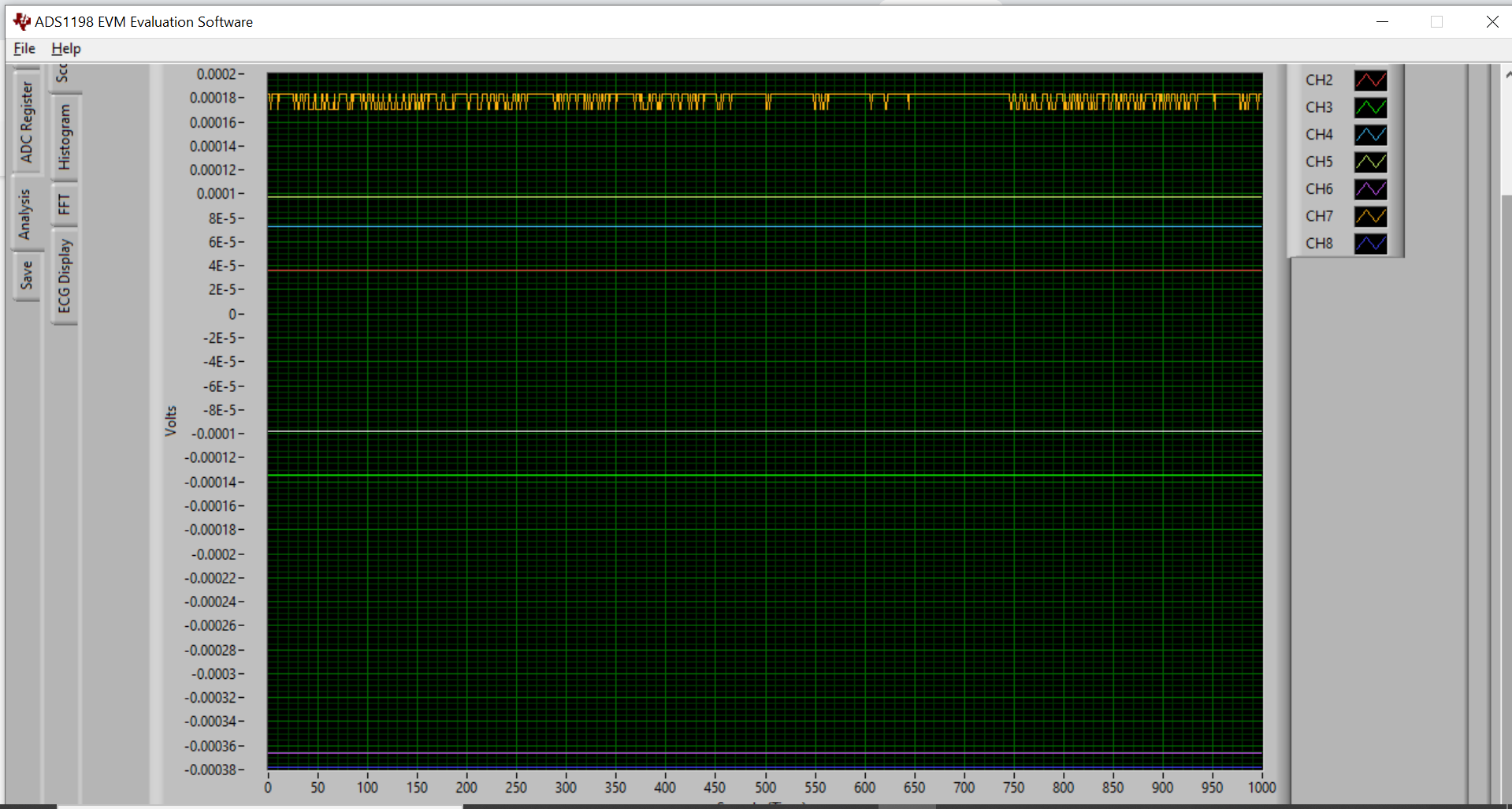
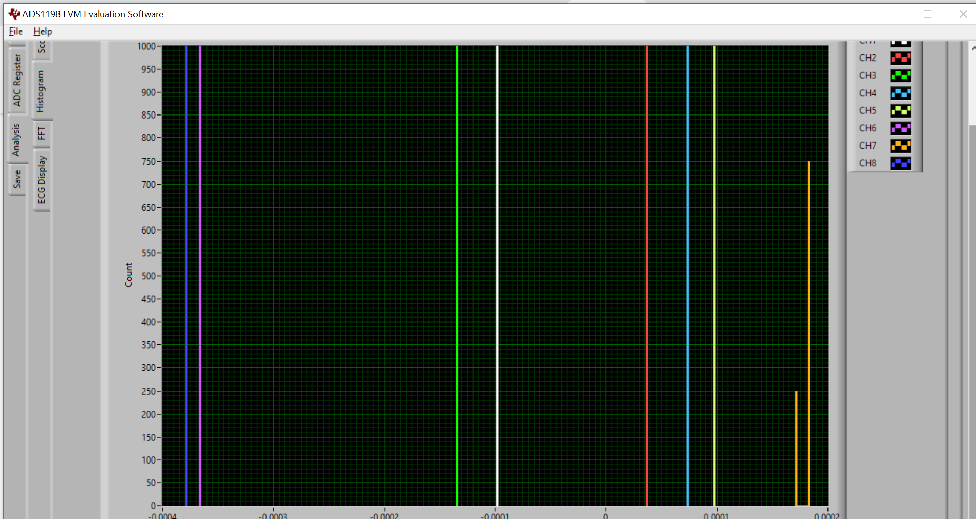
     Thanks so much for replying to my post. I still do not get it as my Histogram analysis tab do not seem to show a Gaussian distribution. I also got noises on different channels each time I acquire the results with the default settings. For example, I would get noises on channels 3 and 7 on the first acquire and noises on channel 1 only on the next. Furthermore, my ADS1198 EVM software does not seem to detect the lead-off detection.

    I have also tried acquiring the same EMG result, which I had successfully gotten previously, using the same settings and connections but the results turned out to be completely different and abnormal. Below are images of my good EMG data where I relax my muscle and then flex at the end.

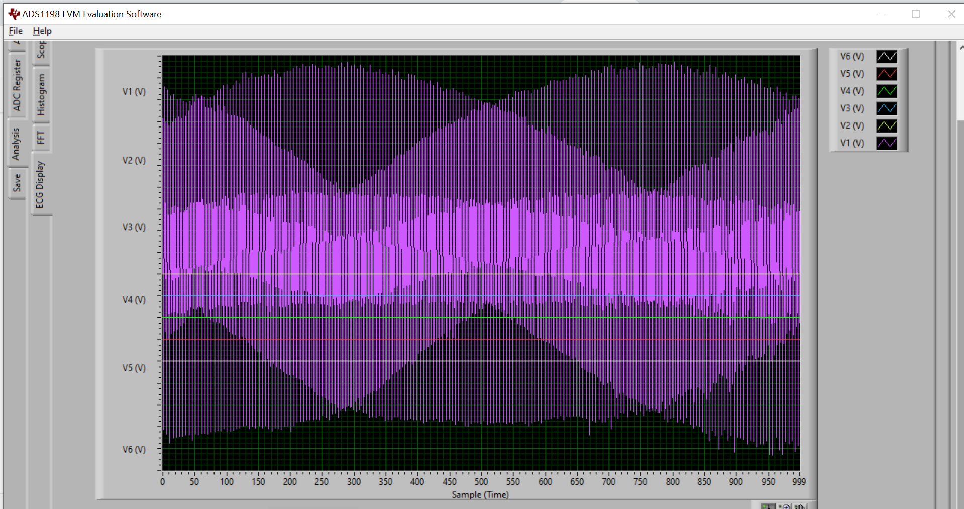
    Below is the EMG data that I am currently getting when I relax and then flex my muscle:

    May you also specify what I could do to solve this problem?

    Thanks once again!

  • Hello Austin,

    Perhaps I misled you a bit on the histograms. For a 16-bit device, it's very possible that all the noise fits into one bin since the LSB size of a 16-bit ADC will be much larger than the LSB size of a 24-bit ADC. This might explain why the Histogram Analysis table shows some unusual Vrms noise calculations (i.e. 216.95E-21 Vrms). The offsets of each channel (i.e. the mean value) seem reasonable to me.

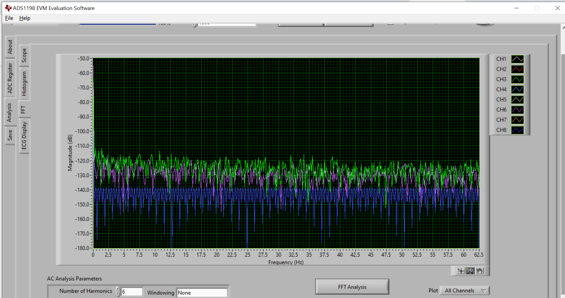
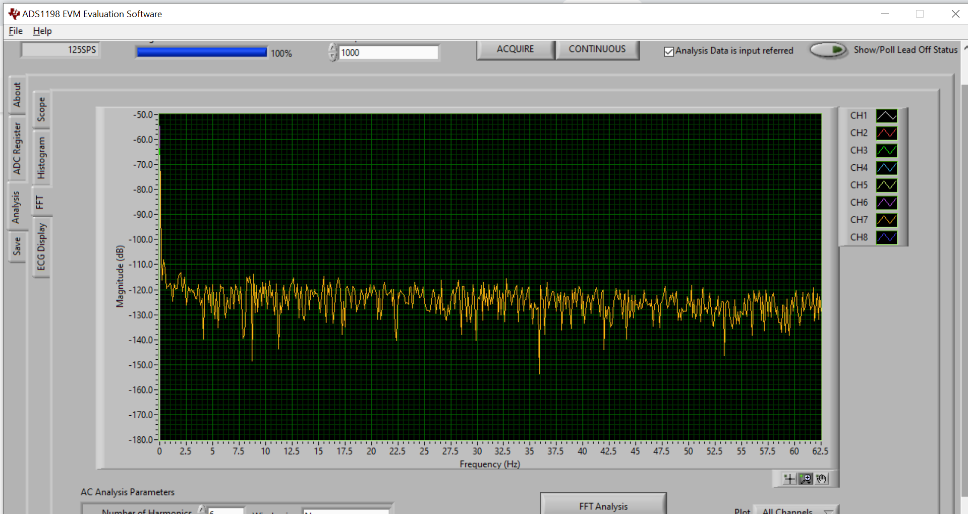
    Between the FFT and the histograms, I don't see a problem with the device. In fact, the noise floor in the FFT looks very flat, which is good. Apart from that, I cannot draw any further conclusions based on the data you've provided. It's not even clear whether the data in one image is related to the others, or what the input signal conditions and jumper/register settings were during the measurements.

    My best suggestion for you at this time is to simplify your testing. Power-down all unused channels and configure their MUX settings as input-short. Remove any unnecessary connections to the inputs and disable accessory features like lead-off detection. You can also replace your EMG inputs with a function generator to provide a known input signal and validate the setup. This would rule out any electrode connection issues.

    Best regards,

  • Hi Ryan,

    Thanks for your help. Just to further clarify your queries, the first 5 images are all related to each other as they are results I acquired using the default settings where all the inputs are shorted(this is the second time I acquire the results on default settings). I just wanted to show you that I got the noises appearing on different channels each time I acquire the results with the default settings by comparing it to the images I first attached above( which is the first time I acquire the results on default settings). 

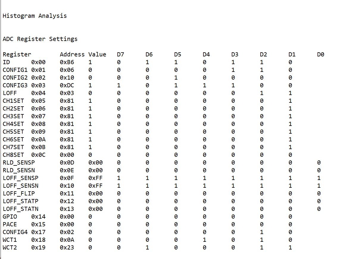
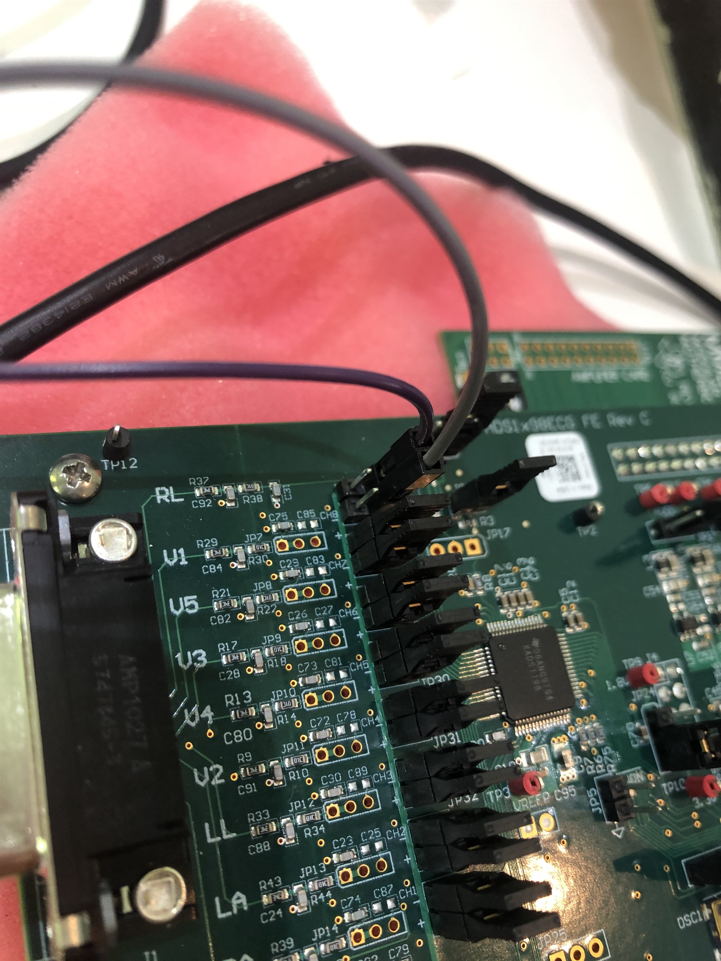
    During my EMG measurements the register settings and jumper wires connections are shown below:

  • Hi Austin,

    Thanks for the images.

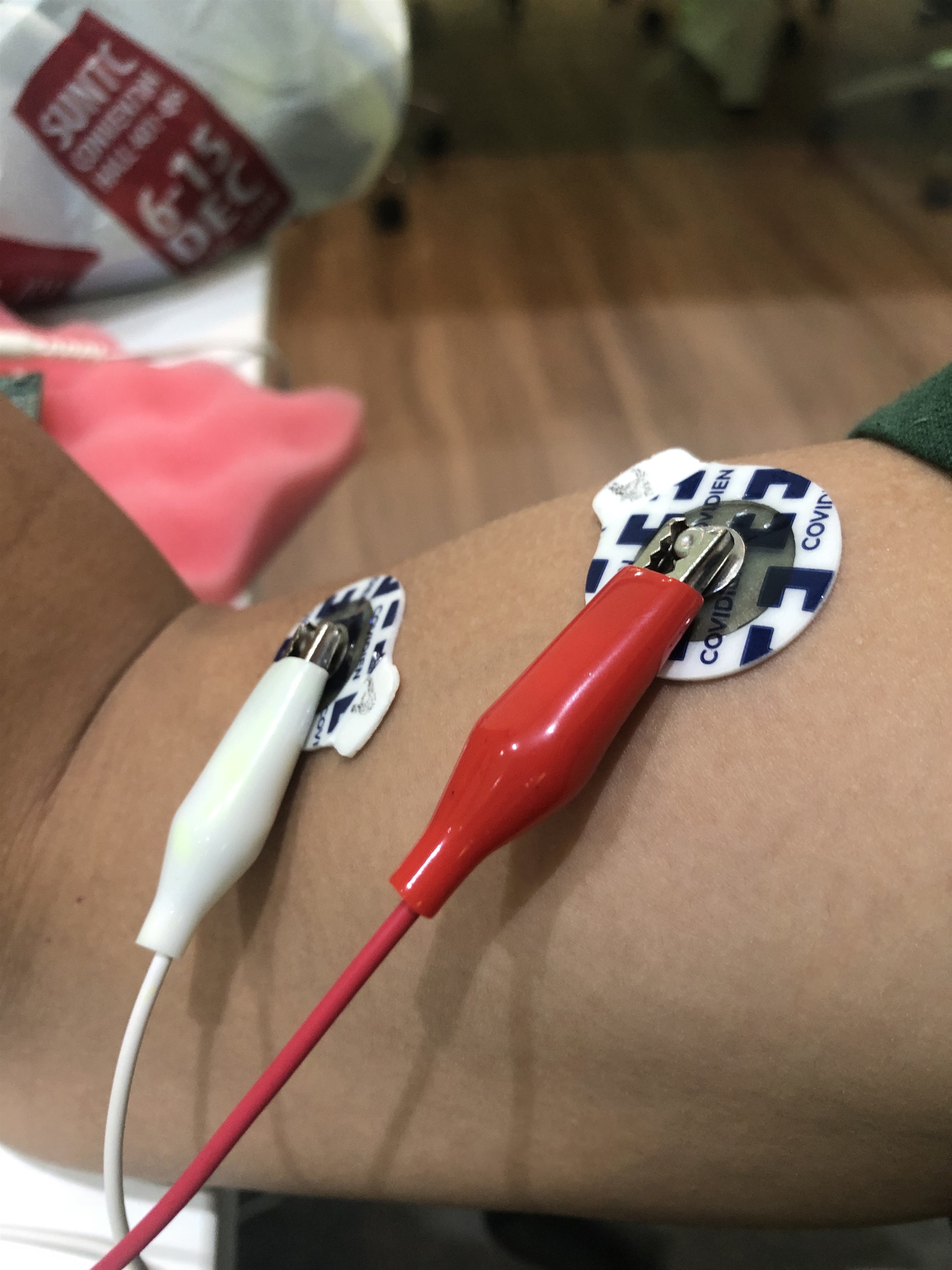
    How are you biasing the input signals? I only see two electrodes connected to IN8P and IN8N. Are you using the RLD? If not, the signals will float relative to the EVM.

    Best regards,

  • Hi Ryan,

    I only use 2 electrodes as I powered on the reference buffer and used it as the internal reference instead of connecting the third electrode. Will that be okay or do I need to connect an external reference electrode to one of the channels?

    Sorry for the late reply.

  • Hello Austin,

    By reference buffer, I believe you are referring to the RLD amplifier (i.e. NOT the internal ADC reference - "VREF" - buffer)? Turning on the RLD amplifier alone will not bias the input signals to a mid-supply common-mode voltage. You will need to connect an RLD electrode, or AC-couple the input signals. You can learn more about this in our online ECG training material (still applicable to EMG) and other resources linked in our ADS129x BIOFAQ page.

    Best regards,