This thread has been locked.

If you have a related question, please click the "Ask a related question" button in the top right corner. The newly created question will be automatically linked to this question.

ADS1298RECGFE-PDK: V6 Graph

Part Number: ADS1298RECGFE-PDK
Other Parts Discussed in Thread: ADS1298R

Hello sir,

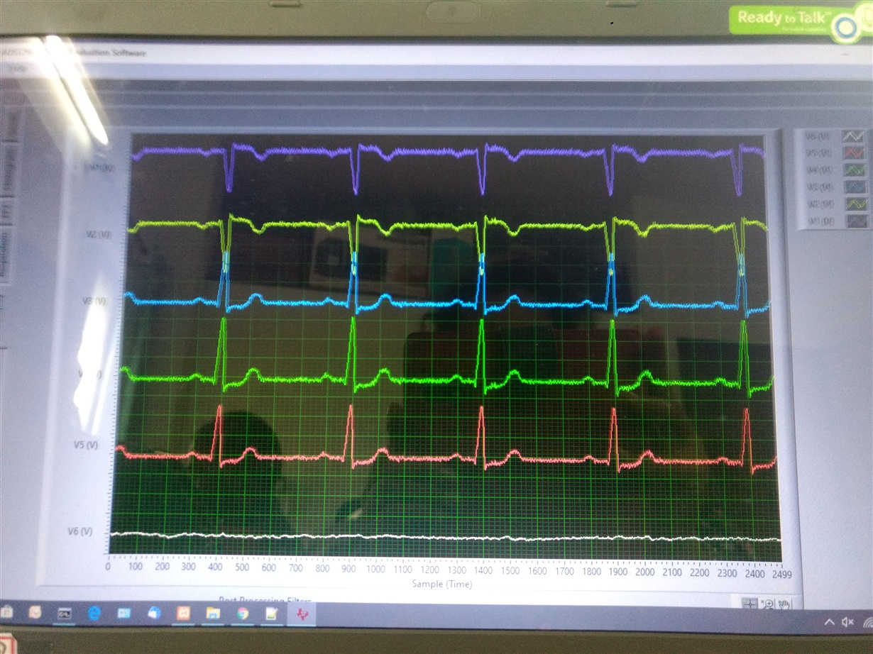
here I am attaching image for chest leads graphs which I am getting on your reference board.

The V6 graph i am getting waveform as shown in the attached image, it's not having any form.

And my query is how should i get it correct or what's the graph structure of V6. I also observed that if I disconnect V6 lead from simulator, in lead off status there is no any change. Changes in limb leads graphs we can see. Can we show V6 lead off status through LOFF_STATP and LOFF_STATN register reading?

Thanks and regards.

  • Hi Koustubh,

    Thanks for your post.

    Please verify the position of the two jumpers on JP33. They should be connected from 1-2 and 3-4. Also, JP16 should be installed.

    If the jumpers are already in the correct positions, can you swap the input signals connected to V6 and V5 from your patient simulator? This will verify whether the issue is with the simulator output or the ADS1298R V6 channel (CH1).

    Best regards,

  • Hello sir,

    Thank you for your Help. Currently I am working on Lead Off Detection part. My question is, when to prefer AC lead off detection?

    Firstly I followed DC lead off detection with this I am getting lead off status for each lead if it's not connected except RL. LOFF_STATP register not showing any change if I not connect RL.

    My current register configuration is,

    LOFF                 0x13

    CONFIG4          0x02

    LOFF_SENSP   0xFF

    LOFF_SENSN  0xFF

    What will be reason behind not showing of RL Lead Off?

    I checked on your reference board with CARDIOSIM II simulator it's showing all Positive Lead Off if RL is not connected.

    Thanks and Regards.

  • Hello Koustubh,

    Did you solve your original issue?

    Please consult some of our training material on ECG applications located on our ADS129x FAQ page for lead-off functions. 

    Regards,

  • Hello sir,

    My first issue was solved, I changed jumper setting and it worked for me, getting V6 graph now,

    I referred the same .pdf file regarding Lead off detection. Using DC lead off detection, LOFF_STATP register not showing any change if I not connect RL.

    My current register configuration is,

    LOFF                 0x13

    CONFIG4          0x02

    LOFF_SENSP   0xFF

    LOFF_SENSN  0xFF

    Thanks and Regards

  • Hi Koustubh,

    It's possible that the inputs are remaining self-biased to ~mid-supply by using a balanced number of positive and negative lead-off current. If all electrodes are shorted together, each channel is forming a 50/50 resistor divider between AVDD and AVSS.

    Best regards,