This thread has been locked.

If you have a related question, please click the "Ask a related question" button in the top right corner. The newly created question will be automatically linked to this question.

ADC128S052-Q1: Channel change issue for ADC128S052-Q1

Part Number: ADC128S052-Q1
Other Parts Discussed in Thread: ADC128S052,

Customer use ADC128S052 to capture negative voltage, the negative voltage is offset by resistance net.

Here are the scenario:

When ADC128S052 just sample Channel 7, the output data is OK;

When ADC128S052 sample Channel 7 and Channel 1, the output data of Channel 1 is OK , Channel 7 is unnormal.

Could you check it for me? Thanks.~~

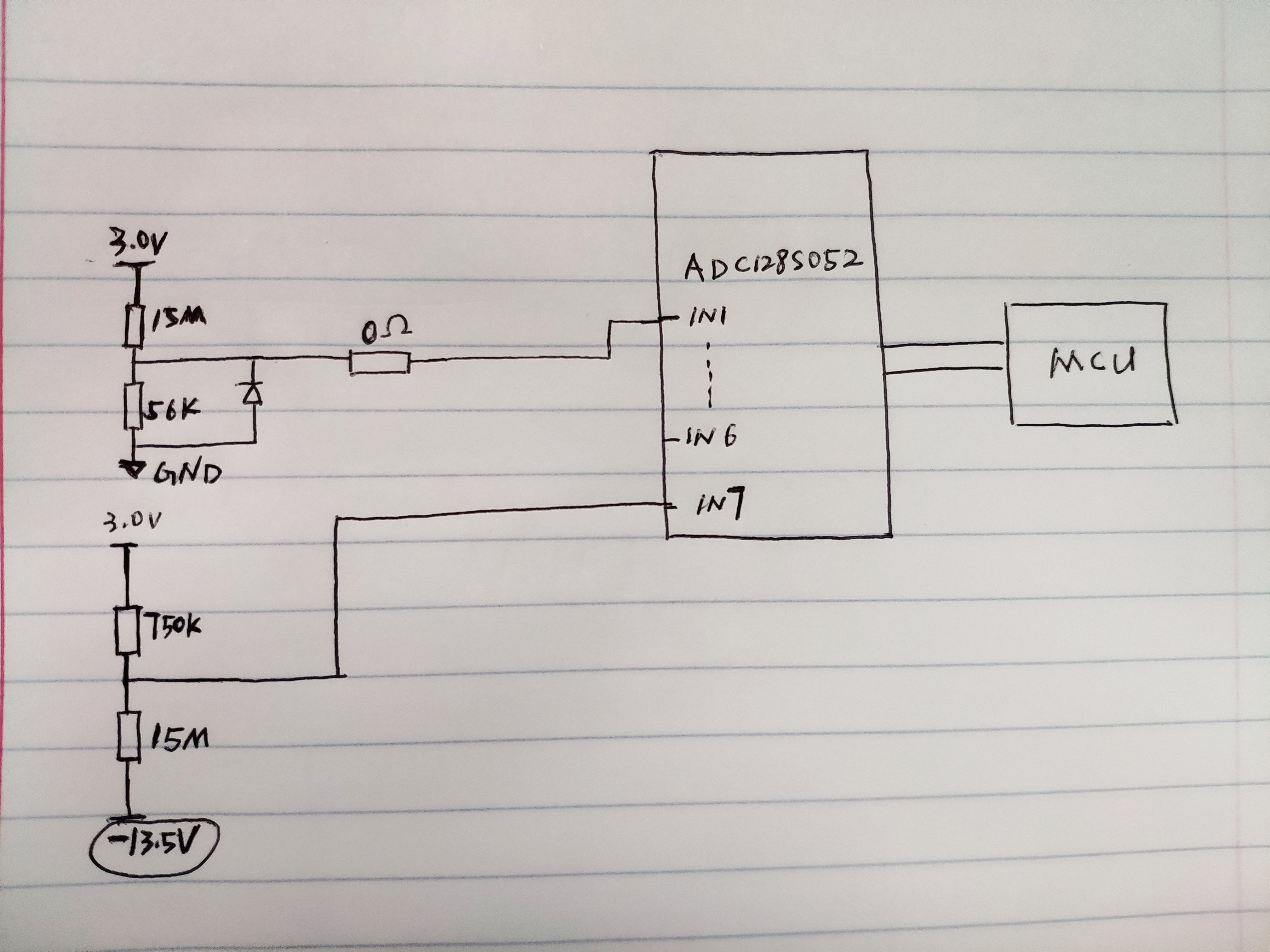
Here is the schematic for ADC128S052-Q1:

  • See attachment for schematic.

  • Hello Songzhen,

    What do you mean by unnormal? Does it look like the input has not settled? As if it cannot reach the full input signal level.

    The input is jumping from 11mV at input1 to 2.2V at input 7 (or vice versa, 2.2V to 11mV)

    This is essentially inputting a step function into the ADC across its full input scale. An ADC cannot respond well to this type of circumstances, especially at faster sampling rates.

    The customer can decrease the sampling rate, to see if input 7 settles when switching channels, and the anomaly goes away

    They can also input a higher input at ch1, say 1V, and see if the anomaly goes away, when switching channels.

    If so, they can change the order of the inputs signals to the ADC, to where the input levels stager and there is no large jump between any two consecutive channels.

    Regards

    Cynthia

  • Hi Cynthia,

    Thanks for your reply.  Could you give us some advice on that?

    There is the scenario like that:

    Scenario 1:

    When we change the sample rate, it still have problem.

    Scenario 2:

    After we change the resistor network for Channel 7, the input resistor and  of channel 7 is same as Channel 1. It works well.


  • 1. Understand, the sampling rate did not help.

    2. yes this worked because you are now using the same input voltage at both inputs.

    To try to explain again

    The input at ch0 is 11mV. The input at Ch7 is 2.2V

    This step is too big change the voltage across the internal capacitor in such a short amount of time.

    1.Can the customer try sampling ch7 more than once during the sequence? for example: Ch0, Ch7, Ch7, Ch7, Ch0, Ch7, Ch7, Ch7, Ch0

    The third ch7 sample should have measurement that is correct. The customer can then discard the first two Ch7 samples.

    2. What are the voltages of the other channels? can they be rearranged in a way that the input voltage levels do not have a change that big2.

    3.Step down Ch7 voltage further if possible

    4. Add a buffer op amp at the input.