This thread has been locked.

If you have a related question, please click the "Ask a related question" button in the top right corner. The newly created question will be automatically linked to this question.

DDC118: Gang 2 channels to share current? We got noise.

Part Number: DDC118
Other Parts Discussed in Thread: DDC232, DDC264

Hey!

We tied a current source to two channels in order to extend the input current range.  It may not be much, but I could double the range if the channels shared the input current well.  If I did my math right, Range 7 (350pC) at minimum continuous integration time (400uS at low power) and nominal Vref (4.096V) gives a max channel current of 3.6uA.  So Imax of 7.2uA if they shared.

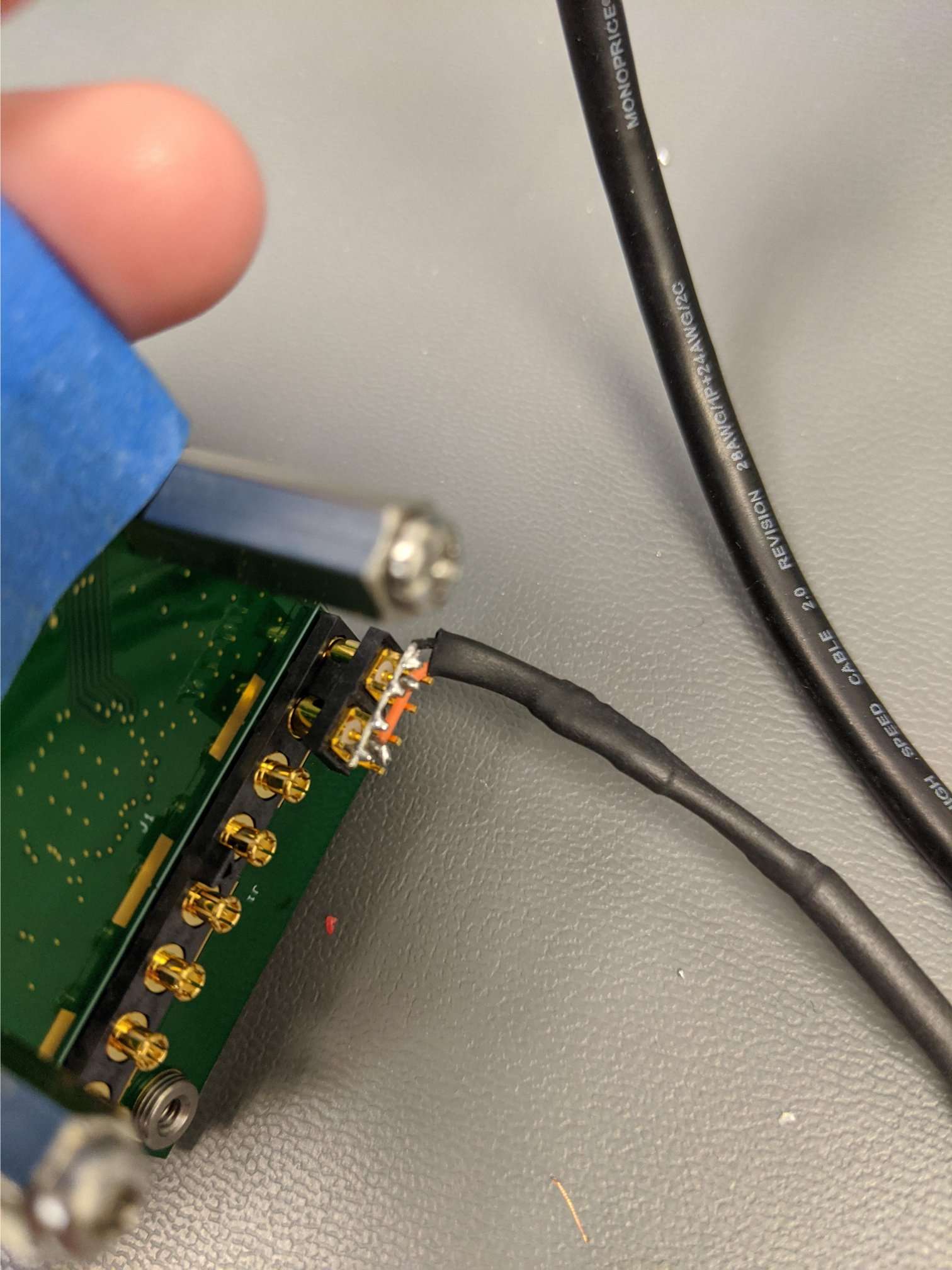
We used channels 1 and 5 which are adjacent on the package, but use different A/Ds internally.  We used a Source Meter to inject DC current and tried fairly hard over several cable  iterations to get leakage & noise controlled.  The DDC118 is on a board of our own design, following TI guidelines reasonably well.  

The did share, but noise went way up.  Sharing gave two channels within 5% of each other, except at very low currents where sharing was uneven.  For an example of noise, at 50nA injected we got:

CH       Avg over 50 samples       Std Dev

1               125 kADU                     261 ADU

1+5           150 kADU                    4580 ADU

My question is:  Why did noise go up so much when sharing inputs?

The noise would ruin the scheme.  The data sheet says all sampling is simultaneous, so we didn't expect switching noise to be a problem.

Thanks in advance!

Paul

  • Hi Paul,

    Before we go into the sharing part, I think there is an error on your full-scale current. 350pC/400us = 0.875uA.

    Not sure why you mention the Vref, but that is already taken into account as part of the normal operation of the device...

    Along the same lines, if you inject 50nA during 400us, it would give you code ~60k (in the 350pC range). I don't know if you meant to say that you were injecting that in each input, but otherwise, something does not match (you got more than 2x that).

    Now about getting double the full-scale, that has some concerns but we have tried it before (on the DDC232, not the DDC118) and it does work (at least to the extend we tried it).

    One concern was that things as you know are not ideal. The two inputs that you are shorting together may not be exactly at the same exact voltage (input bias voltage). When you short them together, effectively you are forcing them to be. One of the things that could happen is that current flows out from one of the two inputs into the other one. If that current is small, it would be just a small offset. In the positive direction (current into the input) it is not a problem. Instead of ~4400 (say that was the offset of that channel) you may get 5500 (for instance). I.e, it would add to the standard offset of that channel. But in the channel outputting the current, it would bring it closer to zero. As long as it doesn't saturate, you would be fine... From the few tests we did in the past it was ok but that is something to check for your device.

    Also, that it doesn't saturate, it doesn't mean that everything is going to be as good as when the inputs were on their own, but I feel that it'll likely be. You could characterize the whole thing as a black box (run INL test, etc) afterwards and see that is doing what you expect... We never got to do that. But anyhow, your noise test is one of those things.

    Other than this I can't think of the reason the noise would increase, as long as you short them cleanly, had everything in a shielded box, etc.  Did you make sure both channels were low noise before doing this? The gain, offset and transfer characteristics of both channels is different but adding them together and measuring at one given input level should basically average out that effect and give you a single output with limited noise (to a first degree, square addition of the two channels noise separately). Did you check which one of the two channels had the noise increase? Or both of them become noisy?

    Regards,
    Edu

  • Hey Edu.  Thanks for the quick, detailed response!

    Yeah, I got my pC and pF mixed up this morning.  Oops, sorry!  I was calculating Q=CV when I already had Q!  

    The data examples I sent were from different settings.  Integration time was 880us, not 400us.  I forgot to mention that, but it explains the ~2x difference.  Sorry to send you on a useless puzzle.

    The main question, the noise:  All the channels were nicely quiet.  Std Dev for all channels ranged from 3.6 to 5.0 counts with inputs open.  Channel 5 was around 4.2 counts.  Channel 1 went from Std Dev = 261 ADU with all the current (50nA) to 2890 ADU with "half" the current.  Channel 5 went from 4.2 to 3090 ADU when we went from floating to tied to Ch1.  The earlier 4580 ADU is from doing the stats on the sum of Ch1 + Ch5.  I'm worse at stats than at calculating max currents, so ... not really sure how to best quote the noise, but it's bad any way I slice the data!  You can see that both Ch1 and Ch5 got noisier.  

    I had read the earlier Forum posts about the offset voltages with data from the DDC232 - it all makes sense.  Like you say, I think we could calibrate out that small, 2nd-order effect.  Thanks for getting that info out to us users - it helps!  We are also experimenting with current dividers to boost range, and we needed to know about the offset to properly size the resistors.  I'm assuming you still don't have data specific to the DDC118?

    Well, I'm relieved to know you don't see an obvious reason for an increase in noise.  So I'm not missing the obvious.  But I'll have to give up on the idea if we can't figure out how to mitigate it...  Thanks again!!

    Paul

  • Hi Paul,

    No issues at all.. 

    One thing that you say doesn't match still, though. When you connect the channels, separately, you go from around 5 to 261. The 5 is along what I would expect, but not the 261. Do you have the possibility to measure the noise without injecting the 50nA but connecting the input physically to whatever you are connecting it? In other words, connecting the input to the source, would add some capacitance, which would increase the noise a bit (depends on range and capacitance, we have some graphs on the DS, if not for the DDC118 you can check newer DDCs). Usually those increments would be far from 261. Also the current source you may have is noisy, in itself? What do you use? And the last option is that you don't have proper shielding and connecting a wire at the input picks up all interference/noise around... We do put our EVMs in a shielded box as certainly the DDC can measure very low level signals so any interferer will do.

    Please clarify that we are good without shorting things, and then we can think more about the shorting, which I still can't think of a reason.

    BTW, using resistor divider is another thing in our task list to try one day but we haven't got to it either.You probably have seen some of the posts in this forum. Should work also but it may add more noise. The input offset (bias) is specified in the DS for very small signal levels. As current increases at the input the value increases because the input impedance of the device is finite, not zero. I don't recall any measurements for DDC118 but you can see some for DDC232 in the forum as well as for the DDC264 on the DS plots. You can get guidance from that... Also, it is a simple measurement to do (just place a multimeter probe at the DDC input while you change the input current...)

    Regards,
    Edu

  • Thanks again for the very timely info Edu!

    It's possible that our physical setup was not optimal.  We use a Keithley SMU which should be a good clean source.  The source cable was Triax, but I'll have to get specifics from the team in lab.  They soldered the center conductor & inner shield right to the DDC PCB input connector (a micro-coax).  I believe the triax outer shield went to the PCB guard planes - but I need to verify.  From the data set I've been quoting, which was our last configuration which we _thought_ was pretty clean, the Std Dev over 50 samples at 0nA input was 23.8 ADU.  So it went from ~4 when open to ~24 when cabled to just Ch 1.  Then up to 261 when we applied the 50nA.  With the triax connected to both Ch 1 & 5, and with the SMU at 0nA injected, the Std Devs were 3390 and 2960, respectively.  I'll try to get photos of the configuration. 

    It just seems weird that this noise increase of an order of magnitude could be from cabling integrity when the cable got us down to 24 ADU when tied to just one channel.  But our team does not have extensive experience with picoamp level circuitry.

    Judging from the number of forum queries about extending the DDC family range by use of current dividers, there is market need & I hope TI can get to it & publish some guidance.  I know the workload is infinite and you have limited resources.  If we get some results, we'll try to share here.  I was going to ask how to measure the offset, so thanks for explaining that!

    Paul

  •  Hey Edu.  Here's a photo of our DDC118 PCB with the Triax attached.  Closest to camera is a bare wire connecting inner shield to the board's coax returns.  Below that is an orange wire used to extend the center conductor & tie the two channels.  I mis-spoke:  the Triax outer shield is not connected.  It is buried under the heat shrink unterminated.

    Paul

  • Hi Paul,

    Love it when people describes things so clearly that we don't need to go back and forth. Thanks for the effort :)

    So, no cable connected is stdev = 4. When you connect the cable and have 0nA, I am assuming the cable still connected to the instrument? You can try without but probably you get about the same. At those levels probably is the cable (I always wonder also if some instruments disconnect the output for 0A). Obvious, but please make sure you don't have any interferers near by the cable (monitor...).

    Regardless, in the past, whenever we tried to source current with an instrument, it wasn't the cleanest. So, your 261counts may be expected. We usually output voltage and use a big resistor (10MOhms) between the instrument output and the input of the DDC, to get a current. This approach is usually very clean.

    Still, nothing of this explains why when you short the two channels noise goes up 10x. All what you do is extend the orange wire to touch the other channel? What do you get with the instrument disconnected or even just shorting the two channels at the input without the long cable (just a small wire short there)? Point being, can you separate the problem on two, the short and the cable and see who is creating it?

    I am not familiar with the triax but assuming the 3rd conductor is external to the shield, I would think it is fine... I assume the shield is connected at both the source and the instrument (else not sure how you would get your return). If it was a differential pair, I would be a bit worried as both wires would not be symmetric. But here, with a current source, I feel it is harder to interpret. We use coax till the resistor which we place on the board. I feel you are going to have to play with different combinations and see, but I am pretty sure we didn't see the increased noise when we shorted two channels. Let me check around, just in case...

    Regards,
    Edu

  • Oh, and forgot to mention that you are right! Tough to get to it, but it is a fun problem and we certainly would like to get to it. We are getting some help in few months, so, this will go in his welcome basket :). In the meantime, thanks a lot for your offering. It'll help others.

    Cheers!

    Edu

  • Hey Edu.

    Good idea to try a simple short between the two channels with no cables, so that they are tied but floating.  It may take a few hours till I get the team in lab to implement it.  (We have minimal staff due to the pandemic.)  We can also try a battery/resistor instead of the SMU.  That is how we tested injection of an offset current (successfully).  I hadn't thought to put the resistor up by the DDC PCB, a wire's length away from the battery.  That would let me put a cap right there too.  Another good suggestion, thanks!  

    I'll get back as soon as we have some results to share.

    Paul

  • Hi Paul,

    Probably you shouldn't put a cap after the resistor (on the DDC side to GND). That will increase the noise gain of the DDC input amplifier. You can see a curve of noise vs C sensor on the datasheet. The cap is also in parallel with a "zero" impedance at the input of the device (although it isn't reality finite), so, it probably wouldn't help either as a filter. In other words, we almost never put the cap... :) (There is one case, when the input are very fast pulses, but it is for a complete different reason).

    Regards,

    Edu