This thread has been locked.

If you have a related question, please click the "Ask a related question" button in the top right corner. The newly created question will be automatically linked to this question.

ADS131E04: Internal oscillator not working

Part Number: ADS131E04
Other Parts Discussed in Thread: ADS131E08

Hello,

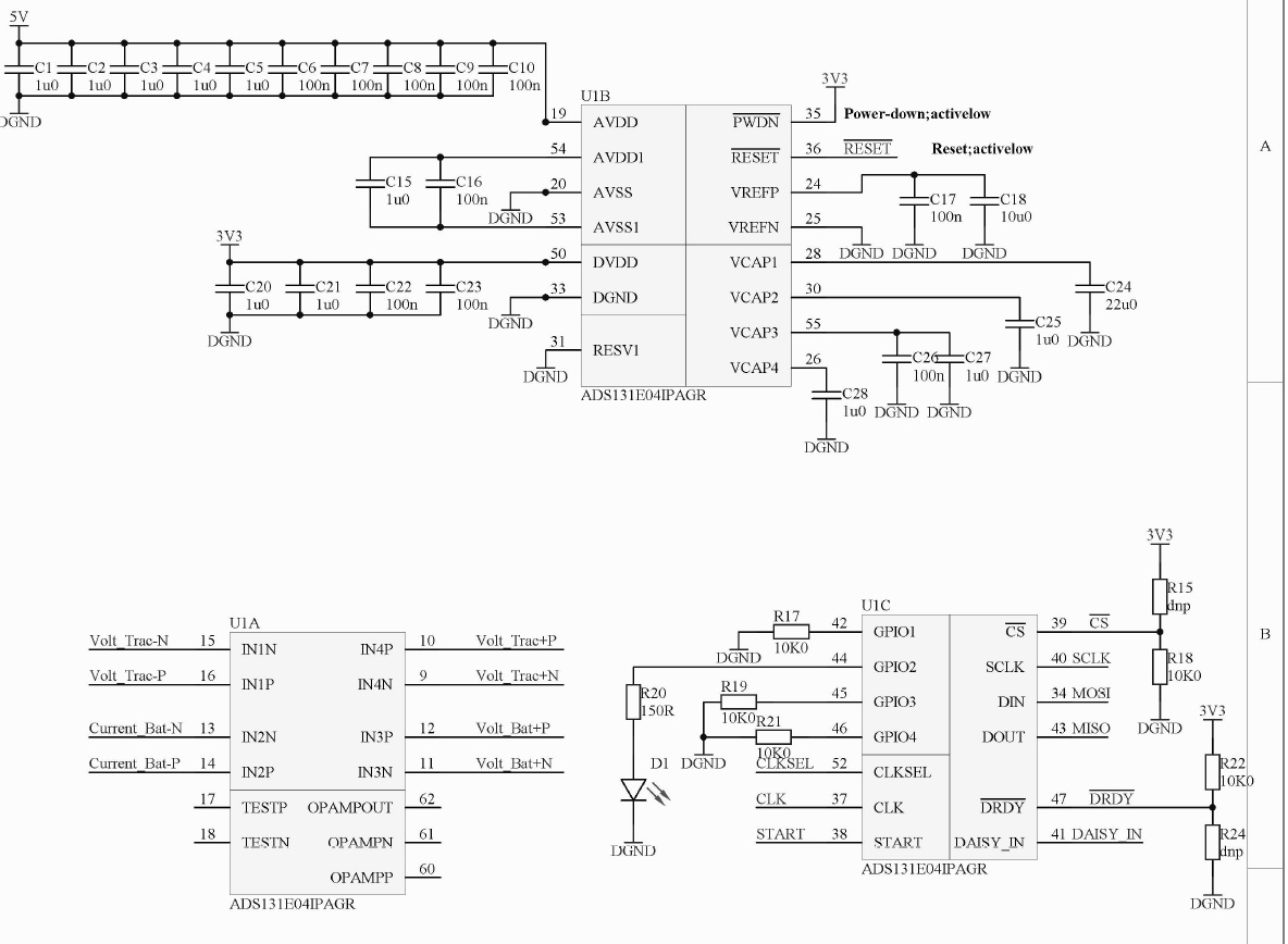
I am having a problem with the ADS131E04. Internal oscillator on the device is not working. CLKSEL pin is connected to 3.3 V and CLK to GND. Device does not respond at all. If I use an external 2 Mhz clock from some other MCU, device responds. In that case I am able to write and read the registers but the ADC values are wrong (read with RDATA 0x12). If I use internal reference, raw ADC values are around 16777000 and if I use external reference values are just random numbers being constantly changed. 

My startup sequence is as follows:

  • CLKSEL = 0 (external clock)
  • PWDN=RESET=1
  • Wait for VCAP
  • Issue Reset Pulse
  • Configure registers:

masterBuffer.txBuffer[0] = 0x41;
masterBuffer.txBuffer[1] = 0x09; // write 10 registers
masterBuffer.txBuffer[2] = 0x96; // cfg 1
masterBuffer.txBuffer[3] = 0xE0; // cfg 2
masterBuffer.txBuffer[4] = 0xC0; // cfg 3 (internal reference)
masterBuffer.txBuffer[5] = 0x00; // fault
masterBuffer.txBuffer[6] = 0x10; // ch1
masterBuffer.txBuffer[7] = 0x10; // ch2
masterBuffer.txBuffer[8] = 0x10; // ch3
masterBuffer.txBuffer[9] = 0x10; // ch4
masterBuffer.txBuffer[10] = 0x87; // ch5 not used
masterBuffer.txBuffer[11] = 0x87; // ch6 not used

masterBuffer.txBuffer[12] = 0x54; // gpio 
masterBuffer.txBuffer[13] = 0x00;
masterBuffer.txBuffer[14] = 0xF0;

  • Send Start command (0x08) and SET START PIN to 1
  • Read all 216 bits with RDATA and parse the data :

// Response starts from masterBuffer.rxBuffer[1]

uint32_t sts = ((uint32_t)masterBuffer.rxBuffer[1] << 16) | ((uint32_t)masterBuffer.rxBuffer[2] << 8) | ((uint32_t)masterBuffer.rxBuffer[3]);
printf("Status: %X\n", sts);
int ch1 = ((uint32_t)masterBuffer.rxBuffer[4] << 16) | ((uint32_t)masterBuffer.rxBuffer[5] << 8) | ((uint32_t)masterBuffer.rxBuffer[6]);
printf("Ch1: %d\n", ch1);

int ch2 = ((uint32_t)masterBuffer.rxBuffer[7] << 16) | ((uint32_t)masterBuffer.rxBuffer[8] << 8) | ((uint32_t)masterBuffer.rxBuffer[9]);
printf("Ch2: %d\n", ch2);

........

If I want to use internal clock, in the sequence above I only change CLKSEL to 1 and after that, no response from the device. Am I doing it right or wrong? What could be the problem?

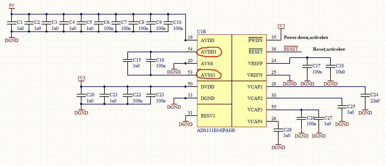
Here is the part of schematic:

Thank you in advance.

  • Irvin,


    There are a couple of things that you've changed for your setup to get it to work. However, it's simpler to work on one thing at a time.

    First, do you want to use the internal oscillator, or do you want to continue to use the external clock. If you want to use the internal oscillator, I would first disconnect everything from the CLK line, and then set the CLKSEL to 1. To be sure, then send a reset to make sure that everything comes up correctly. Then write just to the CONFIG1 register and set the CLK_EN bit to 1. This should send the internal oscillator to the CLK pin. This way, you can observe the clock directly with an oscilloscope. I would start with debugging this clock first if you intend on using the internal clock.

    As for your other comments:

    - If you are getting near 16777000 for output data with the internal reference, this value is close to -1 for the ADC data. The ADC puts out a 24-bit output code in two's complement format. This is explained in the Data Format section of the datasheet on page 33. If you have your inputs shorted, the ADC may simply have a negative offset and you get a small negative number for the ADC.

    - If you switch to an external reference, and you get random numbers, you may not have the external reference connected correctly. If the reference inputs are floating or 0V, you might get bad data.

    Regardless, start with the internal oscillator problems, and we'll move on to the others when you get that working.


    Joseph Wu

  • I tried as you said but the oscillator does not start up. CLKSEL is set to 3.3V and CLK was disconnected and nothing. I am not even able to reach the part where I can write the register CONFIG1 to set CLK_EN bit to 1. I have one LED connected to GPIO so I can see if the register is written. LED stays off. If I use an external clock then it works fine. 

    Is the starting procedure different for internal and external clock except setting CLKSEL pin to 1 and some delay for oscillator to start?

  • Irvin,

    There shouldn't be much difference in starting up for the internal or external clock, the generic procedure would basically be the flow diagram shown in Figure 53 of the datasheet (page 50). 

    I do have one question about the connections to the device. How are AVDD1 and AVSS1 connected? These still require power and should be connected to AVDD and AVSS respectively, and shouldn't be floating with respect to the supplies. Can you attach AVDD1 to 5V and AVSS1 to DGND? I'm wondering if this supply is used for the internal oscillator (among other things).

    Joseph Wu

  • Could that be a problem? You can see how it is connected in the picture below. I can fix this next week and I will let you know if something is changed. 

  • Irvin,


    Yes, that could definitely be a problem. These inputs require power, and currently, there is none. As an example, this image comes from the ADS131E08EVM User's Guide. This is a small part of the schematic from the circuit with the ADS131E08.

    Here, you can see that AVSS1 is connected to AVSS, and AVDD1 is connected to AVDD. 

    Joseph Wu

  • Hi,

    I changed the inputs as you said and now everything is working fine. 

    Thank you very much Joseph.

  • Irvin,

    Just to be completely clear, connecting AVDD1 to AVDD and connecting AVSS1 to AVSS allowed the oscillator to start up? I thought that was the likely problem when I saw the open connection in the schematic, but wanted to be sure.

    Joseph Wu

  • Yes, correct. Internal oscillator is working after connecting AVDD1 to AVDD and AVSS1 to AVSS so no need for an external one anymore. I had a strange ADC values before this fix so I believe that this fix also solved that issue. All ADC values are correct.

    Thank you for helping me solve this problem.