This thread has been locked.

If you have a related question, please click the "Ask a related question" button in the top right corner. The newly created question will be automatically linked to this question.

DAC161S997: output drift issue and device information confirm

Part Number: DAC161S997
Other Parts Discussed in Thread: LM2841,

Dear Reza :

                 how are you?

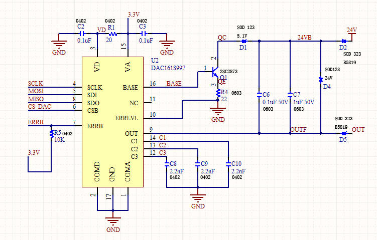
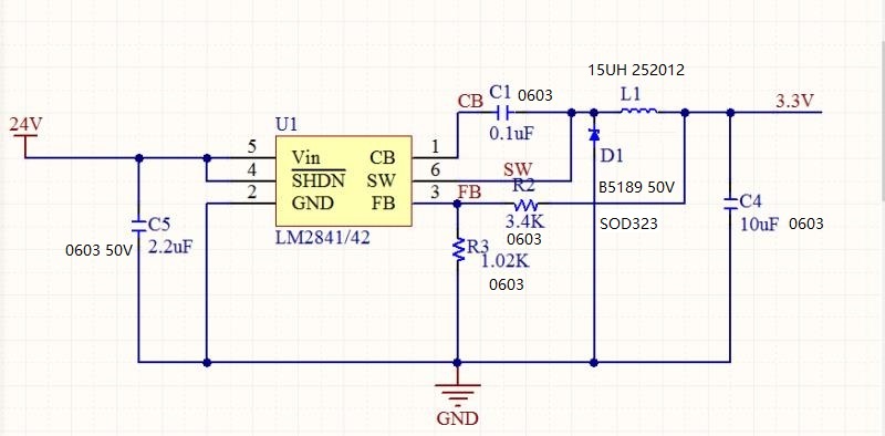
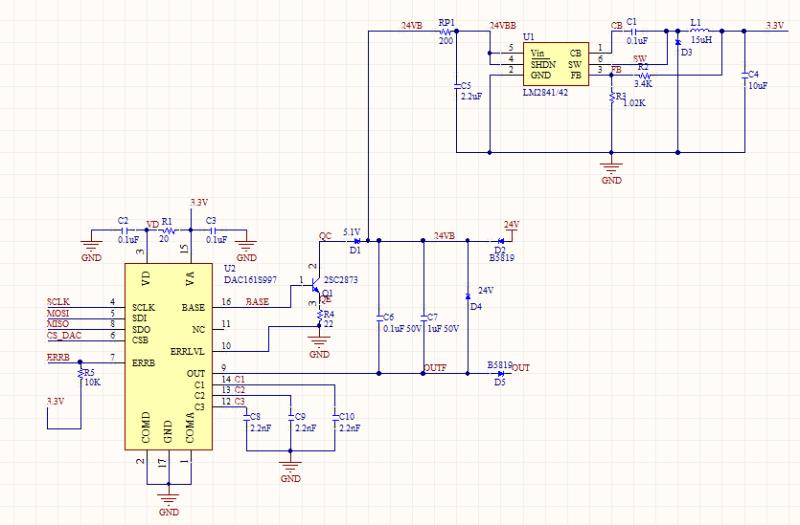
                 I have updated schematic with your suggestion except one resistor as no room on PCB. attached schematic as below. i also added device information on schematic like electrical parameter and package size. very appreciate you help me review it again, are they work? I selected  0402 packages for some device and SOD123 for  D1 and D4 in order to reduce PCB size, is it meet DAC work condition? 

                 I have made some prototype samples with attached schematic , samples worked well just after complete hand soldering. but after some days, i found output current drift, more than 4.1mA at zero point, if add pressure to sensor, output increased . some extreme time, current up to 100+ mA, i don't know why. 

                keep safe!

               thanks 

  • Hello Jeffrey,

    Hope you're doing well. I am quite surprised that the current is drifting even with this updated design. Do you have any other circuits connected to Loop+, 24V, OUT, or BASE? Excess capacitance on these pins could make the loop current unstable and that could manifest itself as drift or abnormal loop current.

    The DAC schematic in isolation looks fine with no concerns to me. Just make sure that all the components are rated properly. C6, C7 for instance should be rated at least 25V and preferably even higher. 

    How are you generating the 3.3V supply for VA, VD?

    Regards

    Reza

  • Dear Reza :

                  thanks !

                 In design system, only Power supply on LOOP+, no any other circuits on 24V,OUT and base. 3.3V supply by LM2841, use suggested typical circuit on datasheet, schematic as below.

                About C6, C7,we selected 50VDC, i think, it should be ok. Dose any other components should i take care when select?   

                We also doubted why samples seem worked well when complete soldering, but after a period of time, it manifest drift, is it related with hand soldering? Does DAC or LM2841 sensitive with temperature? we monitor input to DAC by Uart, at zero, MCU offered mini data10922 to DAC with algorithm control, so output should be around 4mA. 

               thanks ! 

  • Hello,

    I think I noticed the problem. The total capacitance from 24V to GND has to be less than 10nF. C5 = 2.2uF and this is likely making the loop unstable. Are you able to reduce C5 to 10nF and retest? If not, is there a way you can insert a series 200ohm resistor between 24V and C5 to isolate the loop supply from the switcher? This would make the loop stable and I believe may resolve your issue.

    Regards

    Reza 

  • HI Reza :

                 thank you reply so rapid . 

                yes , you suggested me add one resistor into schematic before, i missed it because no enough room on board . ok, i will change it based on your advice . I will make you inform if have any update result . 

                option1. change C5 to 10nF 

                option2: add 200ohm resistor into design . 

               just curious, C5 capatance use for LM2841, why does it impact loop current? if switches output voltage not stable at 3.3V , it should not impact DAC output? because VA ,VD supply voltage from 2.7 to 3.6VDC . right ? 

                have a good day .

    thanks !

    Jeffrey . 

  • HI Reza :

                   as no 10nF capacitance on hand now, so I  removed 2.2uF (C5) from the board first,because we still have C6 0.1uF and C7 1uF before switches. but output loop current increased from 4.25mA to 4.32mA . what's your comments ? in future , i will add 10nF on board when i get it and check what's result?

    thanks!

    Jeffrey

  • Hello Jeffrey,

    Since the DAC operates in a closed current loop system, stability needs to be considered for proper functioning of the loop. All excess capacitance from any node in the loop to the COM pin of the device decrease the loop stability. Capacitance between Loop+ and Loop- improve the stability. This is explained more in detail in section 9.1.1.5.4 of the DAC161S997 datasheet.

    In the current schematic, C5 is connected directly between loop+ and COM and severely degrades the loop stability. This is the reason I suggest reducing C5 to 10nF and also using an iso-resistor between loop+ and the input of LM2841/42. 

    For your next set of tests, can you first repair the board by replacing the C5 and installing the iso-resistor. Then place a new DAC on the board and re-run the test. I believe you wouldn't see any more issues after that.

    Regards,

    Reza

  • Hello Jeffrey,

    Do you have any update on this issue? Were you able to install the iso resistor, replace C5 and test on a new board? I am curious to know if this resolves your the problem. 

    Thanks

    Reza

  • Hello Reza :

                 Sorry for update later. 

                I have done some tests based on your suggestion.  we added one resistor and replace C5 to 10nF together,  but didn't find any impact on output . just after i replaced DAC, output recover to normal. Does resistor significant impact on output ? can I only change C5 to 10nF or smaller (for example 3.9nF) without resistor? 

               we found some strange results when testing . on PCB 1, I removed C5(2.2uF), then i found output changed from 4.088mA to 4. 255mA, after sold C5 to board again, output back to 4.088mA again . so i believe ,  C5 must impact system output result. but on PCB2, we can't find any impact if we remove C5 from the board .it still found zero drift , it can back to normal until we replace DAC , even no C5 on board. but ,after a period of time, system appear drift again. so , we still need verify C5 impact of system , how to stable whole system ?

             BTW , DAC output linear very good, even zero drift, but at other points, still appears the same drifts. 

    thanks!

    Jeffrey 


  • Hello Jeffrey,

    It sounds like you have a couple of issues with different causes.

    1. On PCB1, it is likely that the DAC was possibly damaged from previous testing and it is the reason why the initial loop current is wrong.

    2. For the 2nd PCB, I looked into the datasheet for the LM2841 and it requires a minimum of 2.2uF for C5. That value of capacitance will always make the loop unstable without an iso-resistor so your options are limited. You'll have to insert 200ohm or find an LDO/ switcher that can function with input capacitance less than 10nF. I think that would be hard to find though.

    Regards

    Reza

  • Dear Reza :

                 I very appreciate i  always can get your professional advice. 

                for PCB1, we will try to fix it by replace new DAC .

               for 2nd PCB, still need you help check below questions . suppose we still use LM2841 as power.

          1.   Add an iso-resistor 200ohm, 0603 size with 1/16w,  is it ok?

          2. where is resistor locate ? as your last suggestion? attached picture below, from my understanding, it more like load resistor .  on DAC datasheet, we found it suggest use Capacitance in series with Resistor like picture 2 .  

          3.  how much value of C5, make LM2841 work properly and loop stable ? is 2.2uF work? 

          4. if we use 200ohm + 2.2uF together, what impact does these devices to DAC performance? 

               Sorry, bother you with these questions again, I just want to make sure it, then update design make system more stable. 

               BTW, Do we have any new suggestions for new switch Power fit existing my system? I wouldn't; like LDO, it will generate more heat. 

               Stay safe and have a good day!

    thanks  

    Jeffrey 

  • Dear Reza :

                    what's impact to DAC if LM2841 output unstable , for example , LM2841 output voltage 3V to DAC , what's performance when DAC work at 3V ? 

    thanks !

    Jeffrey .

  • Hello Jeffrey,

    1. The resistor wattage depends on the power consumption of the LM2841 when it is supplying its load. A 1/16W rated 200ohm resistor can deliver about 17mA reliably. That will be sufficient for the DAC but I am not sure if it is sufficient for the other circuits that you power from the switcher.'

    2.  As shown in the datasheet, the iso-resistor should be placed between loop+ and the input to the switcher or LDO. In simple terms, the total capacitance between loop+ and COM should be less than 10nF otherwise a resistor needs to be used to isolate the capacitance from the loop.

    3. The datasheet says the minimum value of C5 is 2.2uF.

    4. Using 200ohm with 2.2uF should not affect the DAC performance. It should make the loop current stable so you can achieve the datasheet specifications of the DAC. 

    Regards

    Reza

  • Hello Jeffrey,

    The LM2841 generates the supplies for VA & VD pins of the DAC. Those pins are rated 2.7V - 3.6V so the DAC should work fine at 3V. However, if the VA pin is switching constantly or is very noisy, this will transfer to the loop current as well.

    Regards

    Reza

  • Hello Reza :

                  thanks for your great support! it is very helpful for us .

                 we have updated our design schematic with your suggestion, will do some testing soon base on it.  will make you informed if any result .

                 BTW, what's accuracy suggestion for resistor and capacitance? how about 10% ? 

                 have a good day !


    thanks !

    Jeffrey.

  • Hello Jeffrey, 

    Thanks for the kind words. The resistor accuracy is not too crucial. A 5% rated resistor should be okay and possibly even 10% rated however I do not know any 10% rated resistors! Similarly, the accuracy of C5, C6 & C7 is not too critical though it helps if ESR and ESL of the capacitors is reduced. The voltage rating of the capacitors is crucial though and should be higher than the loop supply voltage. 

    Regards

    Reza

  • Hello Reza :

                   thanks your professional support. 

                   next, let me try and complete testing.

                  have a good day. 

    thanks!

    Jeffrey