This thread has been locked.

If you have a related question, please click the "Ask a related question" button in the top right corner. The newly created question will be automatically linked to this question.

DAC8740H: Carrier Detection Issue

Part Number: DAC8740H
Other Parts Discussed in Thread: TIDA-060020

Hi,

Application: HART Demodulation at PLC analog input module

Issue: Wrong carrier detection and demodulation signal appears occasionally.

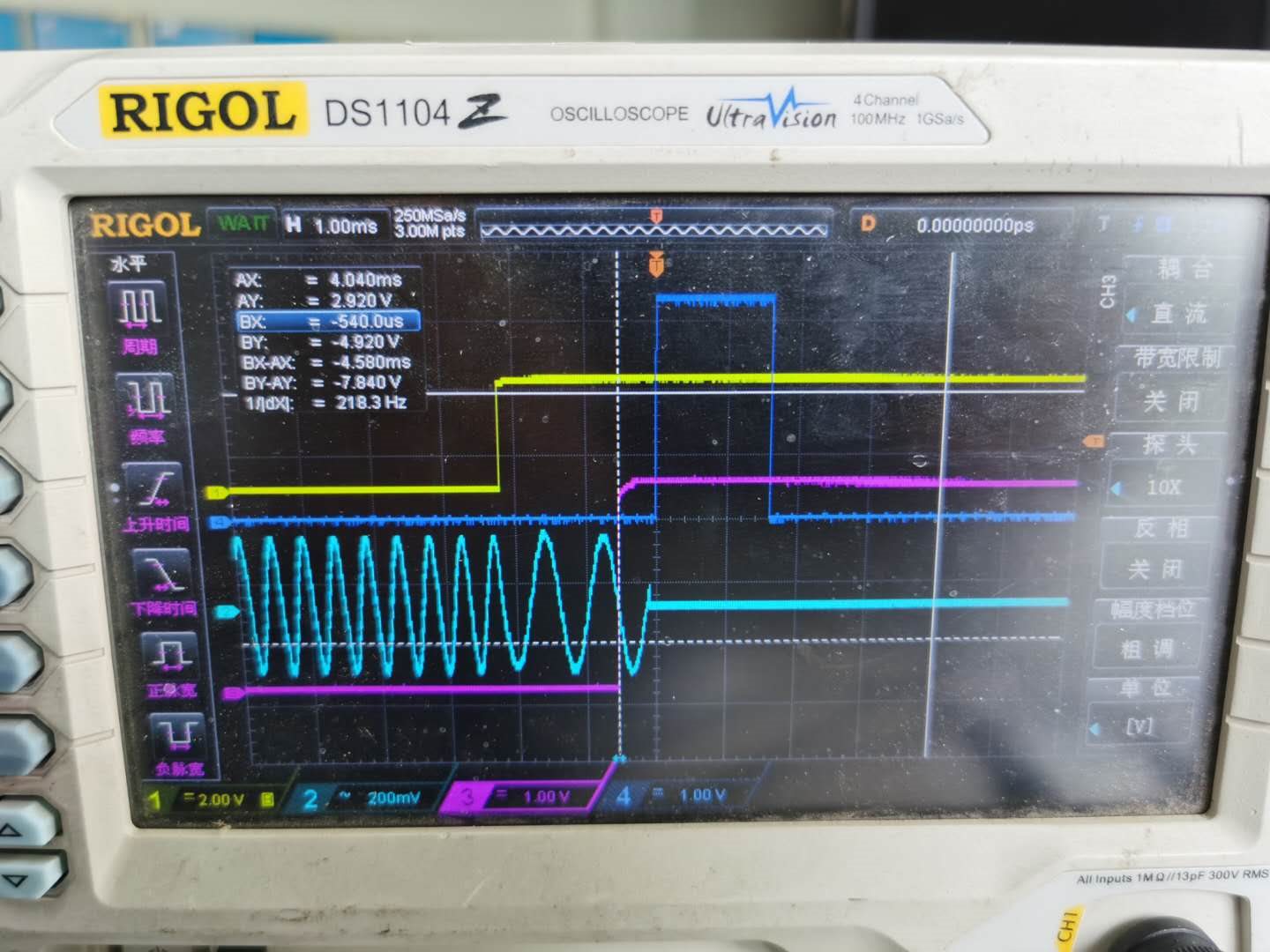
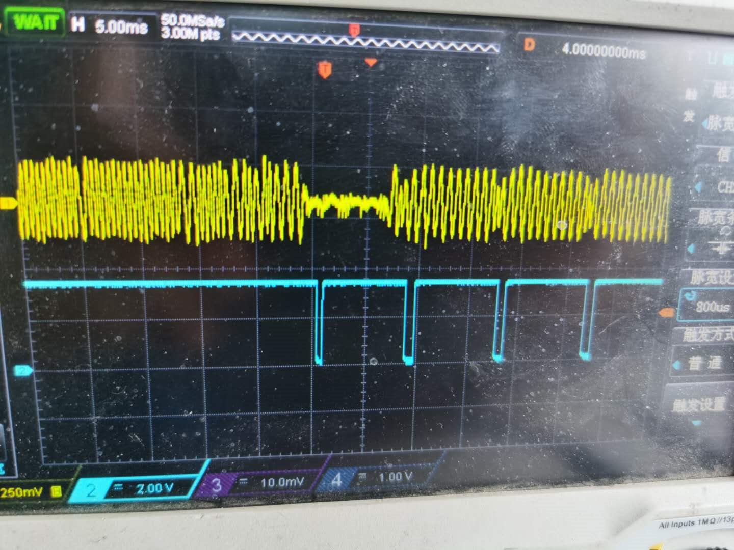
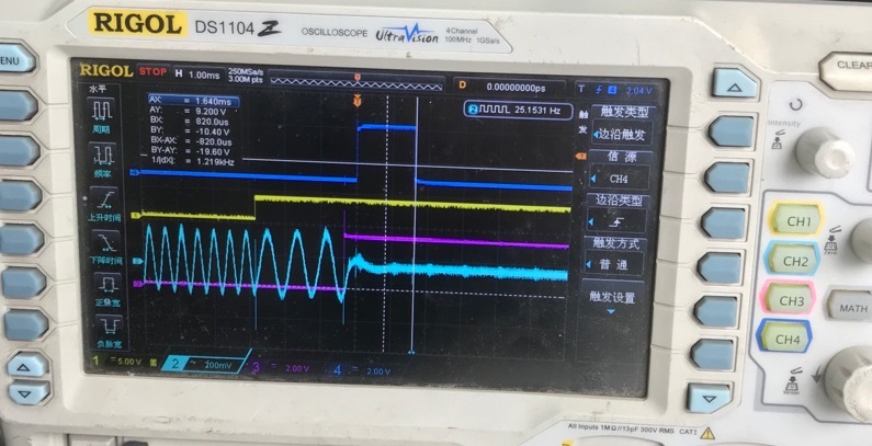
Figure 1: blue- HART carrier signal, deep blue- CD signal ; Figure 2: yellow- HART carrier signal, blue- demodulated signal

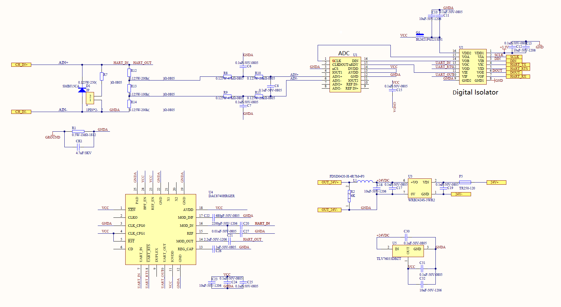
Please find the schematic in the below which is referring to TIDA-060020. Please note the C27 has already been corrected to HART_OUT end on the board.

Questions:

1. The difference between the schematic and TIDA-060020 is that the REF PIN 15 is float rather than connected to ground through 0.1uF cap. Does this may cause the phenomena above?

2. Since the internal reference is selected, is it necessary to ground with decoupling cap?

3. Except the REF aspect, any other suggestion on schematic or test environment for improvement?

  • Hello Tess,

    We recommend having a bypass capacitor on REF pin of 0.1uF or 1uF however I do not think that would cause the demodulation issues you're experiencing. 

    1. What is the yellow trace in the first oscilloscope screen shot? What about the purple trace? It certainly seems like the CD is not active even though a carrier is present at HART IN. Where is the HART IN signal measured? At the pin or across the load or input to the ac-coupling capacitor?

    2. What is connected to the RTS pin? Please ensure that it is high throughout the demodulation phase. 

    3. Do you observe this behavior on a single board or multiple boards? This may help us know if you have an issue with the design or not.

    Thanks

    Reza

  • Hi Reza,

    1. What is the yellow trace in the first oscilloscope screen shot? What about the purple trace? It certainly seems like the CD is not active even though a carrier is present at HART IN. Where is the HART IN signal measured? At the pin or across the load or input to the ac-coupling capacitor? 

    Sorry for the confusion, figure 1 is the Tx stop capture.  Yellow- UART_IN, Pink-UART_RTS, Blue-MOD_IN, Deep blue-CD ; MOD_IN is measured at chip MOD_IN input to the ac-coupling capacitor. 

    2. What is connected to the RTS pin? Please ensure that it is high throughout the demodulation phase. 

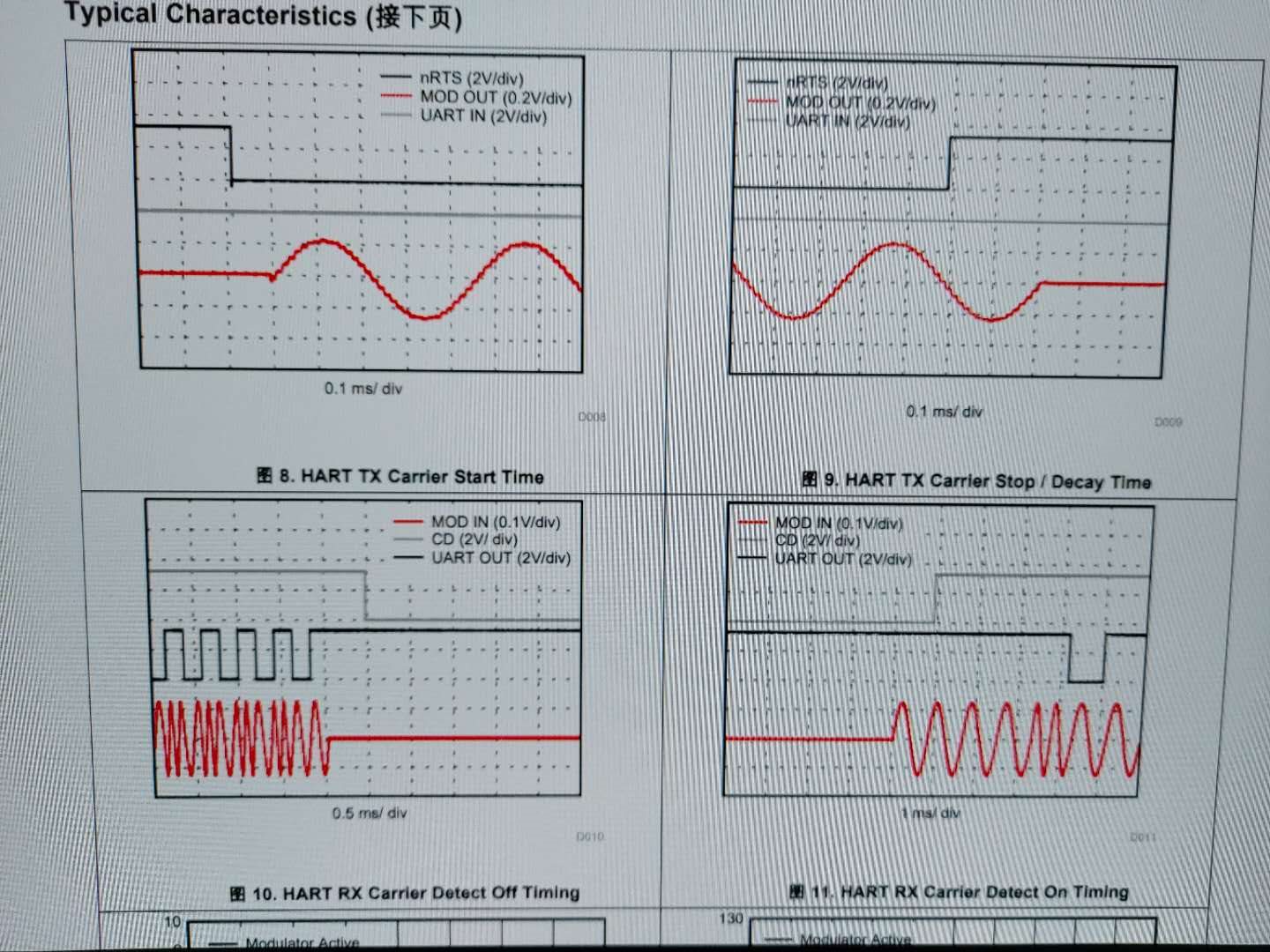
    RTS is connected to digital isolator and then to MCU. The transmission and receive process are valid comparing to the datasheet.


    3. Do you observe this behavior on a single board or multiple boards? This may help us know if you have an issue with the design or not.

    Other board is on testing. I'll feedback to you after.

    Questions:

    1. Figure 1 shows Mod_IN, UART_IN and UART_RTS are respecting the Tx process, but at the stop CD should always keep low state rather than being toggled.  As assumption that Mod_IN  delay and UART_RTS high may cause the wrong CD pulse, another capture is done for validate the delay and amplitude.  It seems repetitive and not a valid carrier detection.  What may cause the CD high without valid carrier?


    2. REF is already fixed with a grounded cap and there is no change in the result.

    3. Duplex pin is recommended float without input in DS but in typical application and TIDA-060020 is connected to ground. Does this may cause something wrong?

    Best Regards,

    Tess 

  • Hello Tess,

    Thanks for the additional information. No digital input pins should be left floating including Duplex. That could certainly cause unexpected issues. Enabling duplex internally connects MOD_OUT to MOD_IN. Under normal operation, HART is half-duplex and only one path should be enabled. I suggest that you connect duplex to GND, ensure that DUP_EN bit in the MODEM_CONTROL register is turned off, and then retest the board. 

    I hope this resolves the issue.

    Regards

    Reza

  • Hi Reza,

    Thanks for your great support and suggestion. The retest with duplex pin grounded is ongoing. Since we found that add a resistor at Mod_out could help and I find TIDA-060020 don't have this kind of resistor. There is a app note https://www.ti.com/lit/an/sbaa306/sbaa306.pdf  which implement the HART on transmitter but I regard there aren't many differences. 

    The resistor I am referring to is R6 in the app note. Could you please explain a little bit about this resistor R6 is mandatory or optional? And why not in the reference design TIDA-060020? Many thanks in advance.

    Best Regards,

    Tess

  • Hello Tess,

    TIDA-060020 is an analog input reference design whereas the app note is for designing a 2-wire loop transmitter. The design topolgies are quite different. For the loop transmitter, the HART output signal needs to be converted into current and added to the loop current. That is what R6 is used for in the app note. For the analog input module, MOD_OUT may not necessarily be required. If it is used, the output signal needs to be directly coupled onto the load resistor of the analog input module. There is no need for an extra resistor for voltage to current conversion. 

    R6 is mandatory for 2-wire loop transmitter design but not for analog input module designs. Any update on the tests after connecting duplex pin to ground?

    Regards

    Reza