This thread has been locked.

If you have a related question, please click the "Ask a related question" button in the top right corner. The newly created question will be automatically linked to this question.

ADS1118: Problem with SPS rate when alternating between internal sensor and ADC channels

Part Number: ADS1118

I  have successfully proven out using a K type sensor on Ch0 and applied compensation using the internal sensor in single shot mode. - so read internal, then read ch0 , work ouit actual temp and repeate. This works fine and I get accurate results.

I have now moved to continuous mode and I'm trying to use Drdy to trigger conversion data. Simply as drdy transitions low, indicating a conversion is complete,  I attempt to read the data (32bit format),. However I find mixed results:

1. When alternating between the internal and ch0 sensor this results in invalid data. - it appears that Ch0 does not respond 

2. If I use drdy to trigger reads, but do not alternate the configuration - for example access just the internal sensor continuously( or access just Ch0 continuously)  then the data received is correct as expected.

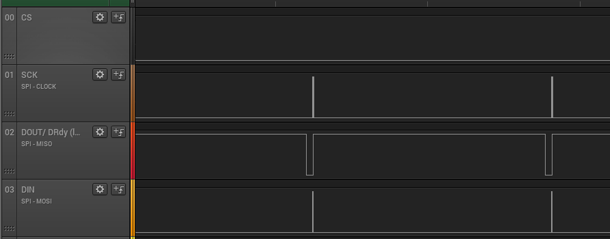
Waveform triggering next read on the 1st DRdy state transition....

3. Here's the "thing", when alternating between each sensor configuration if I ignore the first conversion and then wait for the 2nd (or more) conversions the data is correct - but obviously I half the SPS with this technique. - see below

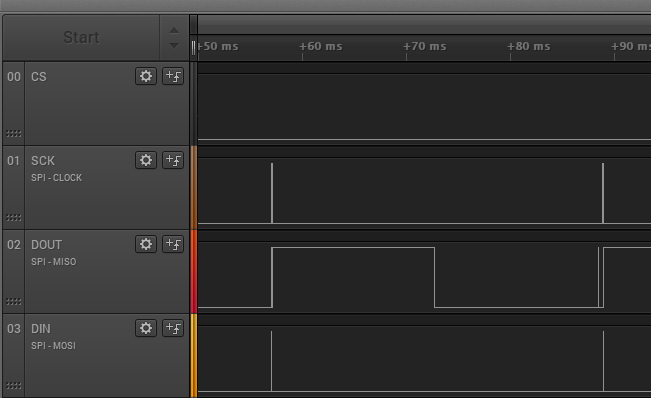
So it seems I cannot attain the full SPS in the configuration if I am alternating between channels and the internal sensor.

Appreciate some input on this.

Regards

  • Hi Norb,

    When running in continuous conversion mode you might assume that writing a new configuration restarts a new conversion, but it is not the case with this device.  The new configuration does not take effect until the current conversion ends and at that time the new configuration takes place.

    The best method here would be to use single-shot mode writing the new conversion when reading the data.  This will achieve the fastest throughput.

    -Bryan

  • Hi Bryan,

    Thanks for your prompt reply. 

    Led by the datasheet it is pretty easy to “assume” the next conversion will be based on the new configuration.

    There is a couple of references to continuous mode and using temperature measurements neither of which indicate that an extra conversion period must be allowed following a configuration change.

    The rate of continuous conversion is equal to the programmed data rate.

    ...acquire one on-chip temperature result, TCJ, for every thermocouple ADC voltage measured

    I would suggest that this behavior could easily be made clear in the data sheet, you nailed a simple one liner above that would be a worthy addition to the data sheet. Or perhaps in the specifications for DATA RATE a note that speeds are reduced in continuous mode when alternating the configuration between reads.

    I will pursue a method using single shot mode, thanks for your input.

    Best Regards.

  • Hi Norb,

    Thanks for the feedback, we will consider this during the next datasheet revision.

    -Bryan

  • Hello sir,

    i am using ads1118 device i have  issue with this i haven input 10 millivolts i am getting more then 10 millivolts around 500micro volts error.(adc mode).  how to resolve this.

    input omv= output 0.250micro volts how to avoid this error.

    actual thermocouple voltage V=Vtc+Vcj  =V=0.200mv=1.119mv. total=1.319mv thermocouple voltage i getting  ,is this right?

    adc mode using formula =read value *fsr/32768 with this i am getting near voltage around.

    but when i apply negative voltage i getting wrong .for negative value is separate formula ?

  • Hi Mahesh,

    What do you mean by negative voltage? Is that when AINN > AINP, such that AINP - AINN <0? Or are you applying true negative voltages i.e. a voltage below ground? You cannot apply voltages below ground to the ADS1118, so please let me know what you are doing.

    -Bryan