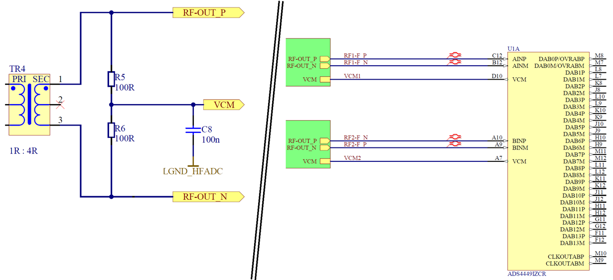
Hello,
i use the ADS4449 in high SNR mode as described in the datasheet. I observe strange offsets which change each time the high-SNR mode is enabled.
In normal operation the offset is basically zero. As soon as I enable HIGH-SNR Mode the offset jumps to some random value between -0.2V and +0.2V. If I don't change the ADC settings, the offset doesn't drift. If I deactivate high-SNR mode, the offset jumps to zero. If I re-enable high-SNR mode for this channel, the offset jumps to some (newly picked) random value again.
This feature is perfectly reproducable with approx. 20 different boards (one ADC per board).
I can even cycle through disable and re-enable high-SNR mode until I am lucky and hit zero offset. Then the offset would stay at zero, but the time of the startup sequence would be somewhat unpredictable in this case.
If I activate test patterns then the values are a perfect match, so there is no error in the digital communication.
Here is my complete initialization sequence after power-up, clocks being applied and hardware reset:
set register 0x00 to 02 (reset)
set register 0x59 to 80 (always write 1)
set register 0xD6 to 80 (always write 1)
set register 0xD7 to 0C (always write 1)
set register 0x71 to 80 (always write 1)
set register 0x89 to 80 (always write 1)
set register 0xA1 to 80 (always write 1)
set register 0xA9 to 00 (clockout delay AB to zero)
set register 0xAC to 01 (clockout delay CD to zero and always write 1)
set register 0x25 to C0 (channel B to 6 dB gain)
set register 0x2B to C0 (channel A to 6 dB gain)
set register 0x31 to C0 (channel D to 6 dB gain)
set register 0x37 to C0 (channel C to 6 dB gain)
set register 0xC4 to 00 (reset fast OVF threshold)
set register 0xC3 to 00 (reset fast OVF threshold)
set register 0x45 to 10 (enable 14-bit mode)
set register 0x3D to 20 (enable offset correction feature)
set register 0xCF to 08 (enable offset correction feature 2)
set register 0x42 to 08 (set digital enable to 1)
set register 0x58 to 20 (enable high-SNR mode Ch A)
set register 0x70 to 20 (enable high-SNR mode Ch B)
set register 0x88 to 20 (enable high-SNR mode Ch C)
set register 0xA0 to 20 (enable high-SNR mode Ch D)
I tested cycling high-SNR mode by using the following sequence:
set register 0x58 to 00 (disable high-SNR mode Ch A)
wait 20 ms
set register 0x58 to 20 (re-enable high-SNR mode Ch A)
wait 1 second
evaluate the DC offset of channel A
Do you have any idea about this?
Best regards
Markus
PS: By the way, there seems to be a small error on page 35, section 8.6.1.10 (SBAS603B – APRIL 2013 – REVISED NOVEMBER 2020), it says:
1 = Digital gain and offset correction features disabled
1 = Digital gain and offset correction features enabled
I just assume that the digital features are disabled when this bit is zero. Correct?


