Other Parts Discussed in Thread: DAC81404, MSP-EXP432E401Y
I was prototyping the DAC81404 evaluation board as it seems to be perfect for my application which requires precise, high-voltage, bipolar DAC.
I do not have MSP-EXP432E401Y Lauchpad developement board so I was using an Arduino compatible microcontroller development board called Teensy 3.6 based on a ARM Cortex M4F microcontroller (Kinetis K66 from NXP) which can be programmed using the Arduino framework. Getting an SPI ready is anyway simple.
For writing to the registers I have this simple function
SPISettings settingsA(4000000, MSBFIRST, SPI_MODE0);

inline void CSON() { digitalWriteFast(DAC_SS_PIN, LOW); }
inline void CSOFF() { digitalWriteFast(DAC_SS_PIN, HIGH); }

void write_reg(uint8_t reg, uint16_t wdata) {
  uint8_t lsb = ((uint16_t)wdata >> 0) & 0xFF;
  uint8_t msb = ((uint16_t)wdata >> 8) & 0xFF;

  SPI.beginTransaction(settingsA);
  CSON();
  //delayMicroseconds(1);
  SPI.transfer(reg);
  SPI.transfer(msb);
  SPI.transfer(lsb);
  delayMicroseconds(1);
  CSOFF();
  SPI.endTransaction();
}
The setup function is simple and I am setting a few registers
void setup() {
  Serial.begin(115200);

  // Chip Select
  pinMode(DAC_SS_PIN, OUTPUT);
  digitalWrite(DAC_SS_PIN, HIGH);

  // reset
  pinMode(DAC_RESET_PIN, OUTPUT);
  digitalWrite(DAC_RESET_PIN, LOW);
  delay(10);
  digitalWrite(DAC_RESET_PIN, HIGH);
  delay(10);

  // Init SPI0
  Serial.printf("SPI0 init...\n");
  SPI.begin();
  delay(100);

  // Write
  write_reg(0x03, 0x0A84); // SPICONFIG: DEV-PWDWN=0
  write_reg(0x04, 0x0); // GENCONFIG: REF-PWDWN=0
  write_reg(0x09, 0x0); // DACPWDWN: DACx-PWDWN=0, x={A,B,C,D}
  write_reg(0x05, 0x0); // BRDCONFIG: DACx-BRDCAST-EN=0
  write_reg(0x0A, 0x5555); // DACx-RANGE=0b0101, i.e. +/-5V

}
Then in the main loop I am simply generating some triangular waveform just to see if everything works fine.
uint16_t i=0;
void loop() {
  write_reg(0x10, (i)%65535 );   // DAC-A
  write_reg(0x11, (2*i)%65535 ); // DAC-B
  write_reg(0x12, (3*i)%65535 ); // DAC-C
  write_reg(0x13, (4*i)%65535);  // DAC-D

  i = (i+64)%65535;
  delayMicroseconds(5);
}
Problem is DAC channel D doesn't update. No matter whatever DACRANGE I choose, it always stays at DAC_AVSS in bipolar mode or at DAC_AVDD in unipolar mode.
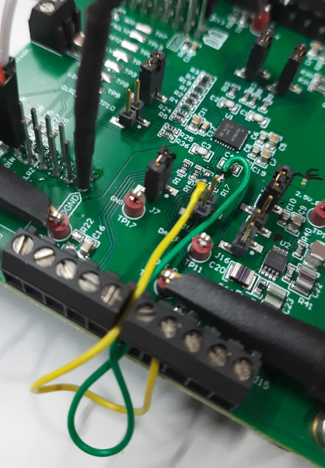
In this case, DAC_AVDD = +12V, DAC_AVSS = -12V, DAC_DVDD=DAC_IOVDD = 3.3V and it is using its internal reference. All the jumpers of the EVM are at their default position except J11 which is configured to provide DAC_AVSS from external sources.
Here's the waveform I get

The DSO channel 1/2/3/4 are hooked up to DAC_VOUT_A/B/C/D TPs. The sense pins are left unconnected. You can clearly the mean value of channel 4 is around -12v and it doesn't change.
What am I missing here?