This thread has been locked.

If you have a related question, please click the "Ask a related question" button in the top right corner. The newly created question will be automatically linked to this question.

Antialias analog passive filter design tools for Precision Data Converter ADS1014

Other Parts Discussed in Thread: ADS1014, ADS1114, TPS92640, ADS1015, ADS1115

Dear All


I' using an ADS1014 (12bit 3.3ksps)  in  a nosily application and I need to design an analog low pass antialias filter for its inputs. Because I don't want to add offset and non linearity to the system I would like to design the input filer with analog components only. Because the converter is put in a feedback control loop should be better if the phase of the low pass filter would be linear enough with the frequency. A need to use the max available bandwidth (3.3k/2 = 1.5ksps)  and an attenuation of 6dB/bit*12 bit = 72dB at the Sigma-delta unknown sampling frequency

1) Does TI has a tools to calculate this filter ?

2) Dows Ti suggest a tools to design such filter ?

2) What is the sigma delta modulator sampling frequency of the ADS1014


Thanks

Paolo

  • Hello Paolo,


    Thank you for your inquiry.  The inputs are sampled at 250 kHz.

    The device uses a  sinc digital filter. Although ADS1014 datasheet does not show the sinc filter response plot, ADS1114 datasheet shows the filter response plot in the TYPICAL CHARACTERISTICS section. The digital filter response plot is shown at 8 SPS data rate, but the plot will hold at 3300 SPS data rate too and the frequency will scale accordingly.

    To achieve 72 dB attenuation at 250 kHz using a single-order low-pass filter, you need to have a -3 dB cut-off at 62.5 Hz. Hence, to utilize the maximum available bandwidth from the device (1.5 kHz), you will have to use higher order analog filter to achieve 72 dB attenuation at 250 kHz.


    I did some quick search and found an active filter design tool:

    http://www.ti.com/lsds/ti/analog/webench/webench-filters.page?DCMP=sva-web-filter-en&HQS=sva-web-filter-filterdesignervanity-en

    I haven't tried this tool myself and hence cannot comment on the quality of the tool.

    Let me know if you have any questions.

    Regards,

    Krunal

  • Dear Krunal,
    Unfortunately the link you mentioned point to a Active filter design tool, so I will ask to my colleague to support with a specific book.
    I don't understand what is the reference to the 62.5 Hz in your answer. May you clarify ?
    Thanks
    Paolo
  • Paolo,

    Thank you for the follow up.

    A single order RC filter rolls-off at 20 dB/decade. Your goal is to achieve 72 dB attenuation at the input sampling frequency (250 kHz). The only way to achieve a 72 dB attenuation at 250 kHz with a single order RC filter is if you set up your cut-off frequency at 62.5 Hz. If you are to use a single order RC filter with cut-off frequency at 62.5 Hz, a single order filter will attenuate your input power further by approximately 20 x log (250 kHz/ 62.5 Hz) = 72 dB at the input sampling frequency (250 kHz). You should be able to get more details on this formula as well as how to design a first order RC filter with a specific cut-off frequency in some books or articles.

    However, you did mention that you want to utilize the maximum available bandwidth from the device. There are two options here:

    1. If you want to use a simple single order passive RC filter with cut-off at 1.55 kSPS, your RC filter will attenuate the signal at 250 kHz further by 20 x log (250 kHz/1.55 kHz) = 44 dB. Is 44 dB attenuation at 250 kHz from your 1st order RC filter acceptable?

    2. If you want to achieve at least 72 dB attenuation at 250 kHz but at the same time ensure that your cut-off frequency is 1.5 kSPS, you might have to use a 2nd order active or passive filter.

    Please keep in mind that the internal digital Sinc filter will also attenuate the input signal. Please refer to TYPICAL CHARACTERISTIC section of the ADS1114 datasheet for the digital filter frequency response.

    Thanks,
    Krunal
  • Dear Krunal

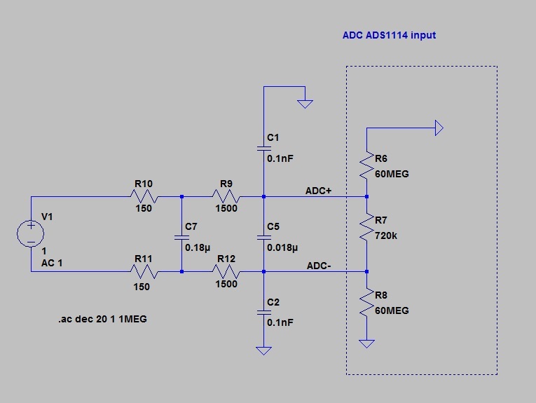
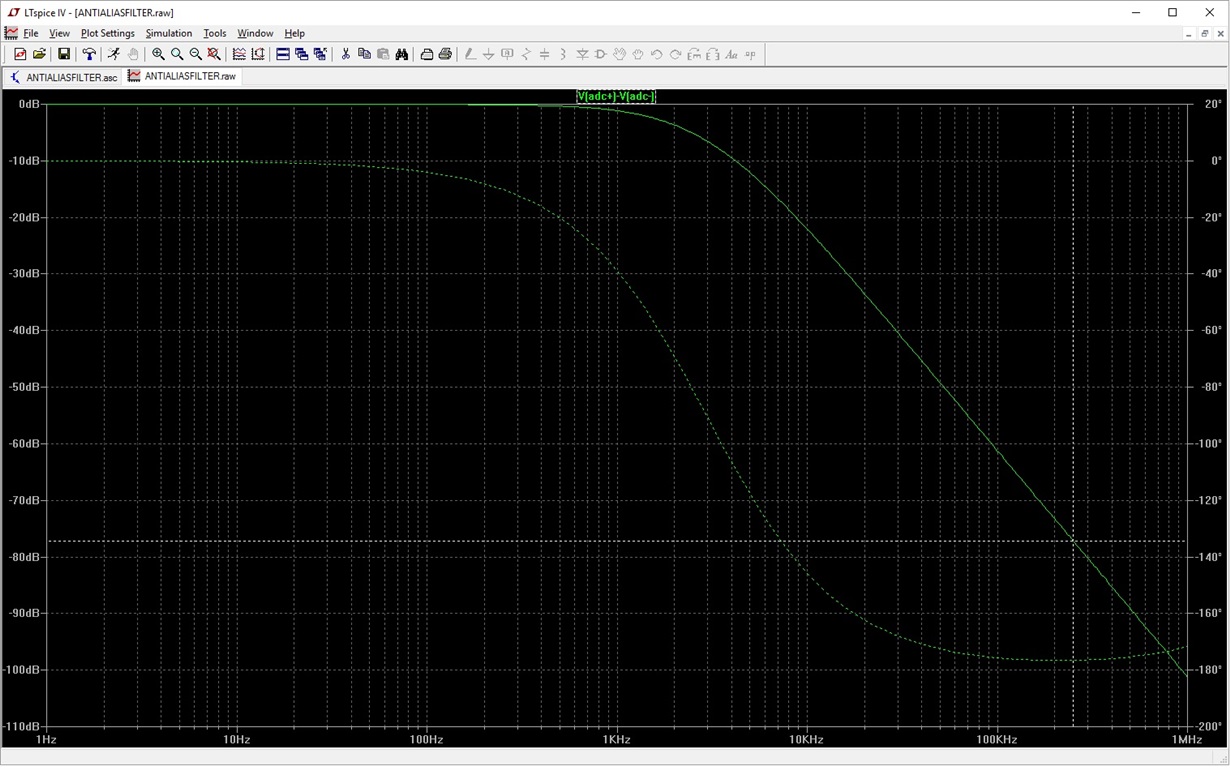
    I designed a 2 pole filter (I skipped the linear phase constrain at the moment, and 1 pole is not enough). See below the solution

    I need to measure a current in a sense resistor of the TPS92640 which  is a 0.2 Ohm resistor connected to ground (in average the current is always positive, however there is ripple even of negative voltage value that the filter will remove @500Khz, Vp = 120mV, I will use the PGA of the ADS set at +-256mV input range). Because there is a lot of noise I would  measure the current with a "sense" differential input of the ADS, one of which is, however, connected to ground. Do you see any problem with the above approach ?

    If I compare the ADS1015 input circuit with the http://www.linear.com/product/LTC2480 LTC2480 input section, I see that the value of the series resistor of the filter can create a error if the input resistance are too high. What do you think about this aspect ?

    Paolo

  • Hello Paolo,

    Thank you for the follow up.

    I would highly recommend to keep the absolute input voltage within GND and VDD. For your case, you are significantly attenuating the 120 mV signal at 500 kHz. So, I guess you are fine here.

    Yes, the series resistor will introduce a gain error in your case. For your case, there is a total of 3000 ohms series resistance. In a 256 mV range, the typical differential input impedance is 710k Ohms and the common mode typical impedance is 100 Mohms. Ignoring the 100 Mohms common mode impedance, a total of 3k Ohms (1500 x 2) will be in series with 710k Ohms. This will effectively introduce a gain error of 3k/710k = 0.0042 = 0.42%. In other words, the voltage across the sense resistor of the TPS92640 will get attenuated by 0.42% as it reaches the ADC inputs. If this is a concern, you can redesign the filter circuit and reduce the series resistance to further reduce this gain error term. For most applications, it is not a concern. You could also consider calibrating out this gain error in your software too.

    Also, keep in mind that the device input impedance changes if you change the full-scale input range and this could change the gain error accordingly.

    Also, the input impedance (or input leakage current) is a function of temperature and hence the gain error would change by a fraction too. ADS1115 datasheet only provides a typical input impedance specification and does not provide any behavior of input impedance over temperature though.

    Thanks,
    Krunal