This thread has been locked.

If you have a related question, please click the "Ask a related question" button in the top right corner. The newly created question will be automatically linked to this question.

ADS6422 start up PLL issue

Other Parts Discussed in Thread: ADS6422

Hi Everybody,

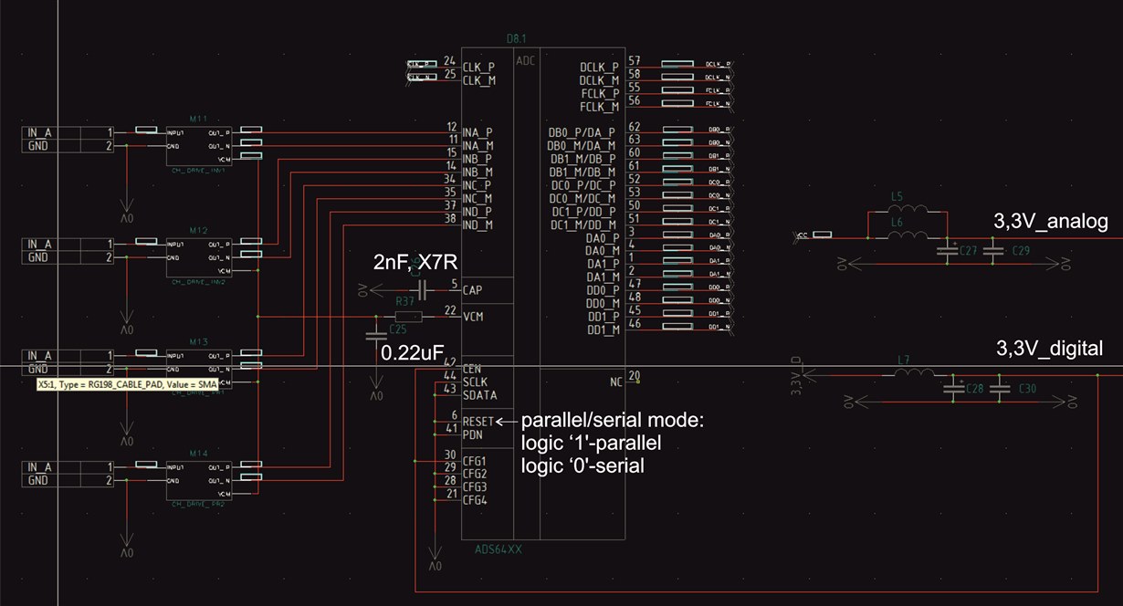
We have an issue with ADS6422  AD converter. The issue is the following. Sometimes without clear logic the PLL inside the ADS6422 can't sturt up correctly. There are 2 cases. The first is we have not nothing at the clk output, the second case is we have pulses at the clk output, but it similar if PLL can't locked. The ADS6422 have the pin, which is connected to external capasitor - 2nf according to the datasheet. There is nothing else about this capasitor in the datasheet.

We have the following statistic.

Totally 28 pcs tested at the temperature range (-40- +55):

- 1 pc - did not start up with nothing at the clk output at the temperature less -30C.

- 1 pc - did not sturt up with not locked PLL clk pulses at the output at the temperature less -15C.

- 2 pcs - first switch on did not start up with not locked PLL clk pulses or/and nothing at the clk output at the temperature less -30C

Totally 63 pcs tested at the normal temperature range (+10 - 25):

- 6 pcs - first switch on did not start up with not locked PLL clk pulses or/and nothing at the clk output at the normal temperature

We need your support with this issue. Have you any recomendation to choose the PLL capasitor. Maybe any other restriction or application notes for ADS6422 regarding our issue.

We use parallel programming in the both mode(serial/parallel programming option according to the datasheet). After the powering on the IC start up with parallel programming set after that we do not use serial programing and don't reset internal registers.

Hope for your prompt reply and support. Thanks in advance.

  •  follow the shematic we use

  • Vitaliy,

    I'm moving your post to the correct forum
  • Vitaliy,

    We are looking into this.

    Regards,

    Jim

  • We have the statistic updates.

    Another 42 pcs tested at the temperature range (-40- +50):

    - 3 pc - did not start up with nothing at the clk output at the temperature -40C and +50C.

    - 1 pc - did not start up with nothing at the clk output at the temperature -40C.

    - 4 pcs - first switch on did not start up with not locked PLL clk pulses at the temperature +40- +50C.

    Any ideas?

  • Please update my request.

  • Vitaliy,

    Sorry for the delayed response. The design team did not report any issues based on the temp testing you have done. Please let me know the following so we can assist you more with this issue:

    How are Reset, SEN, SCLK, SDATA, PDN and CFG1-4 connected? These are all used during parallel programing mode.

    Is there an output on FCLKP/M when this problem occurs?

    Is the board powered off, soaked at a cold temp for a period of time, then powered up?

    Are all voltages at the correct level when problem occurs?

    Can you send us your schematic? If not, how about just the ADC portion?

    What are you using to measure the output clock with?

    What is the source of the input clock? Is it at the proper frequency and level at the input pins when device fails? Is there a chance the part goes into Clock Stop mode, as described below from the data sheet? 

  • Hi Jim,

    Thanks for your reply.

    Regarding schematic, please check it in my previous post. I have attached the schematic of ADC part.

    We don't use serial programming option. But Reset pin is tied low. According to the datasheet it is no problem. It must start by parallel programming option first and then if you need to use serial programming you need make a pulse on the reset pin and then programm registers.

    When the problem occurs there are 2 cases on FCLK pins. It is 0 (nothing), logic '0'. The second case is not locked pulses. It seems like PLL can't locked.

    Yes the board is powered off, soaked at a cold temp or heated for period of time, and then powered up. If we try to cold down or heat up the powered on board, there is no problems occurs in all the temperature range.

    Both voltages logic and analog power wires are correct levels. Both switched up simultaneously. We use TPS70302 LDO to make AVDD 3.3V from 5V source. And for LVDD use direct 3.3V from power source. For both LVDD and AVDD we use LC filters.

    The source of input clock comes from FPGA in LVDS. Yes the frequency is proper - 20Mhz. It is ok (according to the datasheet 5-65Mhz). But FPGA need some time to programm from the Flash memory first, after that the PLL in ADC lock the CLK.

    We use oscilloscope Tektronix with 500MHz bandwidth and 2.5Gs/s.  

  • Vitaliy,

    The data sheet mentions the RESET must be held high if using parallel programming mode. Please try this as this may be your problem.

    Regards,

    Jim


  • Jim,

    Unfortunally our pcb have connection of RESET pin to 'gnd' under the chip. So, we must reflow the chip if we want to try this. But according to the datasheet, there is the both parallel and serial programming option. At the first start up parallel programming is used after that serial programming option may be used or not by reseting the registers at the first by logic '1' pulse on RESET pin. So we just use the first half of this mode - parallel programming and nothing at the second step.
  • Vitaliy,

    If you have RESET tied to GND, you must pulse it using software. It appears you are never issuing a true reset and this may be your problem. Do you have any way to write to the reset register? If not, can you lift the RESET pin from GND and connect a wire to it then pull it high?

    Regards,

    Jim

  • Hi Jim,

    Unfortunally it is hard to lift the RESET pin from GND, cause of need to reflow the ADC IC. But we plan to do it on the following boards, before assembling.

    Anyway, according to the datasheet, we don't need to issue the reset after powering up. If we issue the reset, all the registers will be cleared to their default state and will be necesssary to reprogram it via serial interface after the reset.

    Moreover we have this issue with several pieces of ICs (15%). Have any advices for sequence of LVDD, AVDD voltages? We try to close these 2 wires and for some pieces this can help.    

  • Vitaliy,

    I am checking with the design team about this.

    Regards,

    Jim