This thread has been locked.

If you have a related question, please click the "Ask a related question" button in the top right corner. The newly created question will be automatically linked to this question.

LMK04828

Other Parts Discussed in Thread: LMK04828

Hello,

TIers!

For each port of lmk04828, the default frequency division number is not the same, and we found that the normal frequency division range of different ports is also different. For example, when the frequency division number of dclkout10 is less than 3 and greater than 9, the output waveform will be distorted. So we want to ask about the frequency division range of different ports? Are they divided into high frequency output and low frequency output?

Best regards,

David

  • Hi David,

    My coworker will get back to you by tomorrow.

    Regards,
    Hao

  • Hi,

    It is true there are different default output dividers. Refer to register 0x100 and other registers definitions in column "POR DEFAULT".

    You mentioned the waveform was distorted, please notice the duty cycle correction (DCC) function for output format..

    Search key word "duty cycle correction" for details register settings.

  • Thanks!

    After my debugging, I have another problem about LMK04828.

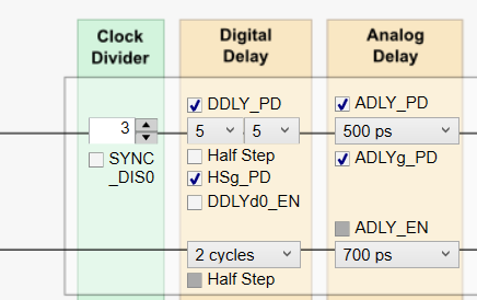
    This picture is in LMK04828 software.

    1.What's the function of SYNC_DIS0?After I set it 0,the waveform distortion is serious. I have to set it to 0 to adjust the digital delay, otherwise the digital delay cannot be adjusted.

    2. Can I set it to 1, and then adjust the digital delay?Because we can get a better waveform in DCLKout0 by setting it to 1.

    Best regards,

    David

  • The SYNC event must occur for digital delay values to take effect.

    Step 1, Set digital delay value;

    Step 2, Set SYNC_DIS0 =1 to make OUT0 will respond to SYNC operation; Other synchronized channels also can be set 1.

    Step 3, Toggle SYNC pin, to toggle SYNC_POL bit, to trigger SYNC; Digital delay will be valid;

    Step 4, Clear SYNC_DIS0=0; OUT0 would not response to SYNC operation in case there are some interfering on SYNC pin.

  • Thanks for your help!

    em...What't the unit of digital delay?As shown in the  picture,digital delay is set as 5,5 ,how long is this delay?Such as ms or ps?

  • The digital delay allows a group of outputs to be delayed from 4 to 32 VCO cycles. The delay step can be as
    small as half the period of the clock distribution path. For example, 2 GHz VCO frequency results in 250 ps
    coarse tuning steps. The coarse (digital) delay value takes effect on the clock outputs after a SYNC event.
    There are 2 different ways to use the digital delay.
    1. Fixed Digital Delay - Allows all the outputs to have a known phase relationship upon a SYNC event. Typically
    performed at startup.
    2. Dynamic Digital Delay - Allows the phase relationships of clocks to change while clocks continue to operate.

    See details in LMK04828 datasheet section "9.3.3 Digital Delay".