This thread has been locked.

If you have a related question, please click the "Ask a related question" button in the top right corner. The newly created question will be automatically linked to this question.

ADS124S08EVM: Read just 0xFF when used STM32 to connect board ADS1x4S08 Evaluation

Part Number: ADS124S08EVM
Other Parts Discussed in Thread: ADS124S08

Hi Team,

Posting this inquiry on the customer's behalf:

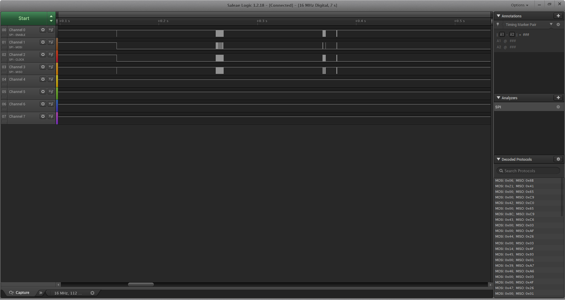
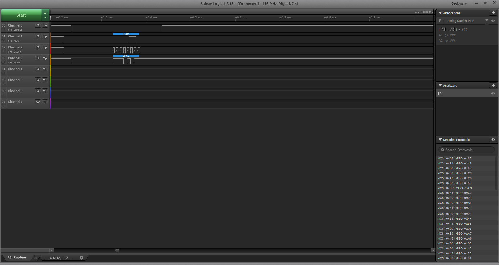
They plan to connect some STM32 machines to a ADS1x4S08 Evaluation and use SPI by communication through via J3 on board.

As they want to measure voltage signals between 0 and 5V, they used a voltage divider to get our signals to 0-2.5V.
For the Software, they am using an adapted Version of the ADS124S08.cpp/ADS124S08.h by Jens Chr Brynildsen
But when read register and data just all 0xFF.

int32_t InitDevice_ADC()
{
if( MX_SPI_Init() != 1)
return -1;
/* Default register settings */
registers[ID_ADDR_MASK] = 0x08;
registers[STATUS_ADDR_MASK] = 0x00;
registers[INPMUX_ADDR_MASK] = 0x89;
registers[PGA_ADDR_MASK] = 0x00;
registers[DATARATE_ADDR_MASK] = 0x14;
registers[REF_ADDR_MASK] = 0x1A;
registers[IDACMAG_ADDR_MASK] = 0x00;
registers[IDACMUX_ADDR_MASK] = 0xFF;
registers[VBIAS_ADDR_MASK] = 0x00;
registers[SYS_ADDR_MASK] = 0x01;
registers[OFCAL0_ADDR_MASK] = 0x00;
registers[OFCAL1_ADDR_MASK] = 0x00;
registers[OFCAL2_ADDR_MASK] = 0x00;
registers[FSCAL0_ADDR_MASK] = 0x00;
registers[FSCAL1_ADDR_MASK] = 0x00;
registers[FSCAL2_ADDR_MASK] = 0x40;
registers[GPIODAT_ADDR_MASK] = 0x00;
registers[GPIOCON_ADDR_MASK] = 0x00;

sendCommand(RESET_OPCODE_MASK);
HAL_Delay(100); // ms
sendCommand(WAKE_OPCODE_MASK);

HAL_Delay(100); // ms

sendCommand(START_OPCODE_MASK);


if( regRead(ID_ADDR_MASK) == 0x01 ) // check device ads124s08
return -1;
HAL_Delay(10); // ms

for( int i = 0; i < NUM_REGISTERS ; i++)
{
regWrite(i, registers[i]);

}
HAL_Delay(10); // ms

data2 = regRead(DATARATE_ADDR_MASK);
readRegs(0,NUM_REGISTERS);

return 1;
}
main()
{
if(InitDevice_ADC() < 0)
while(1);


uint8_t dStatus = 0;
uint8_t dCRC = 0;

HAL_Delay(100);

/* Read out the results */

data = dataRead(&dStatus, &dCRC);
}

Please let me know if you have any questions with the customer.

Thanks,

Jonathan

  • Hi Jonathan,

    To use the J3 connector, the micro on the EVM must be held in a reset state.  This requires that the jumper JP1 be installed on the EVM.  Also on the EVM the RESET pin must also be pulled high and not floating.  How is the EVM being powered?  I recommend plugging in the EVM to USB on the PC to power the board.

    Best regards,

    Bob B

  • Hello Bob,

    Thank you for your support and the answer you have provided.
    This works for the customer but currently has a problem when they read registers of the ADC configuration is not as expected.

    They used logic analyzer of oscilloscope then the result same as on the app to read.
    So please give a few suggestion.

    Bellow is the code.
    - JP1 installed
    - RESET pin pulled high
    - START pin pulled low

    registers[ID_ADDR_MASK] = 0x08;
    registers[STATUS_ADDR_MASK] = 0x00;
    registers[INPMUX_ADDR_MASK] = 0x8C; //Set MUX to AIN8 & AINCOM
    registers[PGA_ADDR_MASK] = 0x00; //Disable PGA
    registers[DATARATE_ADDR_MASK] = 0x14; //Set Datarate:disable G-Chop,internal CLK,Continous Conversion, Low-Latency Filter, Datarate:20SPS
    registers[REF_ADDR_MASK] = 0x39; //disable Ref-Monitor, disable positive reference buffer,dis. neg RefBuf,select ref input pins,dis. inter
    registers[IDACMAG_ADDR_MASK] = 0x00;
    registers[IDACMUX_ADDR_MASK] = 0xFF;
    registers[VBIAS_ADDR_MASK] = 0x00;
    registers[SYS_ADDR_MASK] = 0x13; //enable CRC- and Statusbit
    registers[OFCAL0_ADDR_MASK] = 0x00;
    registers[OFCAL1_ADDR_MASK] = 0x00;
    registers[OFCAL2_ADDR_MASK] = 0x00;
    registers[FSCAL0_ADDR_MASK] = 0x00;
    registers[FSCAL1_ADDR_MASK] = 0x00;
    registers[FSCAL2_ADDR_MASK] = 0x40;
    registers[GPIODAT_ADDR_MASK] = 0xF0;
    registers[GPIOCON_ADDR_MASK] = 0x00;


    sendCommand(RESET_OPCODE_MASK);


    if( regRead(0x1) == 0x80 )
    {
    regWrite(0x1, 0x40);
    }
    for( int i = 0x02; i < 18 ; i++)
    {
    regWrite(i, registers[i]);

    }
    HAL_Delay(10); // 1s

    readRegs(0,NUM_REGISTERS); // Read the registers of the ADC configuration

    sendCommand(START_OPCODE_MASK);


    Please let me know your comment.

    Regards,

    Jonathan

  • Hi Jonathan,

    I really don't see anything wrong with what they are doing, but there could be an issue related to timing.  There should be a delay following both the RESET pin set high as well as when sending the RESET command.

    It would be helpful to see the logic analyzer shots of the communication for me to review.

    Best regards,

    Bob B

  • Hi Bob,

    This is logic analyzer singal sreen of project above.

    Please let me know your comment.

    Best regards,

    Doi

  • Hi Bob,

    I added time delay following both the RESET pin and RESET command.But when I read registers of the ADC configuration is not as expected.

    bellow is code I add delay.

    sendCommand(RESET_OPCODE_MASK);
    HAL_Delay(10); // ms

    HAL_GPIO_WritePin(GPIOJ, GPIO_PIN_7, GPIO_PIN_SET);    // set pin reset to High
    HAL_Delay(10);
    HAL_GPIO_WritePin(GPIOJ, GPIO_PIN_7, GPIO_PIN_RESET);  // set pin reset to Low
    HAL_Delay(10);

    if( regRead(0x1) == 0x80 )
    {
    regWrite(0x1, 0);
    i = 5;
    }
    for( int i = 0x02; i < 18 ; i++)
    {

    regWrite(i, registers[i]);

    }

    HAL_Delay(10);

    readRegs(0,NUM_REGISTERS); // Read the registers of the ADC configuration
    HAL_Delay(10);

    sendCommand(START_OPCODE_MASK);

  • Hi Jonathan,

    Thanks for the logic analyzer shots.  It tells the story well.  Note that the data transmitted to the device (MOSI) is changing on the falling edge instead of the rising edge.  The data must be stable on the falling edge and change on the rising edge.  Note MISO where the device is changing on the rising edge.  Your communication should match the correct phase as shown on MISO.

    Best regards,

    Bob B

  • Hi Bob,

    Thank you so much about this support!

    Now STM32 communication with ADS124S08 work well.

    Thanks and best regards,

    Doi