This thread has been locked.

If you have a related question, please click the "Ask a related question" button in the top right corner. The newly created question will be automatically linked to this question.

ADS1263: Could not read the ADC value, but can read back the registers

Part Number: ADS1263

Hi all!  Can someone please help?  I am using the ADS1263 EVM daughter card.

I can write and read back successfully from the registers.  But when I read the ADC value, all 6 bytes were 0 including the STATUS and CHECKSUM !

I chose the pulse conversion mode.  The START signal is every 2 ms. (channel 1)

The DRDY goes low after 1.2 ms after started. (channel 2)

Then I read the 6 data bytes at once, but all 0. (channel 3 is the SCK, and 4 is the DOUT)

I got it work before.  One day it failed as described above.  So I replaced the ADS1263.  Remained the same.  May be I made some mistakes in the software accidentally, but the register values are the same.  Seems not software problem.

I just found I could not read back the registers when the CLOCK SELECT SWITCH was on the XTAL side.  And I probed at pin 15 and the crystal pin, no oscillation found.

Then I switched to use INTERNAL oscillator, it worked as described above.  Will it be the cause?  Or it is another problem?

Thank you for helping me to solve these problems. Thank you!

  • Hi Kenny,

    What happened to cause the board to fail initially? That is most likely the root cause of the issue you are seeing, if the board worked well for some time and then stopped working. I would try to recall what happened at that point to cause the failure. Please let me know.

    I would also make sure the power supplies are connected appropriately and that there is a strong, stable ground connection between the daughter card and the communication board, since the daughter card is meant to be hard connected to the MMB0 motherboard.

    Please let me know what caused the board to fail originally.

    -Bryan

  • HI Bryan,

    Thanks for reminding me to check with the MMB0 motheroard.  Let me find the cable and let you know later.

    The power supplies are good, 3.3V, +/-5V. (Same result for both +5V and +/- 2.5V)

    The amplifier in front of it is working at +/-15V.  So I suspected the input voltage was too high that the input part was damaged.  But it remained the same after the ADS1263 was replaced, and the amplifier voltage were lowered to +/-2.5V.

    The SPI is working in both directions as it can read back the registers to compare.

    FYI.  Here is the function ReadADC().  It is called once DRDY_ pin goes low.

    //////////////////////////////

    void ReadADC() {
        //read the converted result
        //6 bytes in RxBuf[];
        //[0] is the status,
        //[1..4] is the converted result.
        //[5] checksum.

        unsigned char i;

        //Read the data from ADC
        Pin_ADC1_CS_ = 0; //Chip select the ADC
           for (i = 0; i < 6; i++) { //Rx 6 bytes, Status and also checksum
             _Clr_SPI_Rx_Buf_Full; //SPSTA &= ~RCVBF; //clear the buffer full flag

             SPDAT = 0; //to initiate SPI
            while (SPI_receiving()) { //(SPSTA & RCVBF) == 0) { //wait till 1 byte received.
              _nop_();
            }
           RxBuf[i] = SPDAT;
        }
       Pin_ADC1_CS_ = 1;
    }

    ///////////////////////////////////

    This seems to be correct, right?

    Thanks for your help!

  • Hi Kenny,

    Can you tell me how you are powering the ADS1263 daughter card? Which voltages are connected to which pins?

    Also, there is no amplifier on the ADS1263 daughter card that required +/-15V, so can you please explain what this means? Do you have an amplifier somewhere external to the EVM?

    Can you also read back your registers and post the results here?

    You can also see that there is noise on DOUT and START when you issue the SCLKs. This probably indicates a poor connection between your motherboard and the daughter card.

    You mention that you read 6 data bytes, but you are only issuing what looks like three groups of 8x SCLKs, or 3x bytes.

    -Bryan

  • Hi Brian,

    Thanks for your feedback!  Here are the answers to your questions:

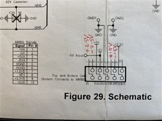
    1.  The powering to the ADS1263 daughter card:

  • Hi Brian,

    Thanks for your feedback!  Here are the answers to your questions:

    1.  The powering to the ADS1263 daughter card:

    This is the same for all the other daughter cards such as the amplifier and filter.  Hope that the +/- 15V on pin 8 & 9 won't damage the ADS1263 card.  Pin 1 & 2 are connected to the AVDD and AVSS from ADS1263.  This supplies to the external amplifier and the strain gauge.

    2. Yes, the amplifier is external.  It was powered from +/- 15V.  Now changed to +/-2.5V as said above.

    3. I do read back the registers to compare.  The result is +ve as I could break at the point where the comparison is right.  Please see my code.  Seems this tells that the SPI is correct.  (I inserted the code,but it said "Access denied", "I have not the right ...")

    4. Thanks for pointing out the noise on the DOUT line when the SCLK is pulsing.  Will fix it.

    5. I checked with the scope.  There were 6 sets of SCLK seen when the time base was increased from 250 to 100us.  So really 6 bytes were received.

  • Hi Kenny,

    Can you post some pictures of your whole system? It has become less clear to me how you are actually connecting all of these different PCBs. I assumed you were not using the MMB0 board since you original post asked specifically about the ADS1263EVM daughter card, but now I am not so sure.

    Also, can you please provide the register read back settings here? I would like to see all of the registers values for all of the ADS1263 registers.

    -Bryan

  • Accidentally it is working now!

    Today I plug the daughter card on the MMB0 motherboard.  It worked!  So the daughter board is proven to be OK.

    Then put back to my motherboard, it worked also!  I do not know why yet.

    FYI.  These are the 15 registers I wrote to the ADC:

            code const unsigned char ADCsetting[] = {

                    0x00,               //Reg 0x1, 00000000      level shift voltage diabled, internal reference disabled

                    0x0D,               //Reg 0x2, 00001101      SPI timeout, STatus byte needed, checksum enabled

                    0x41, //0x51,  //Reg 0x3, 01010001      Pulse conversion, chop, 8.7us delay

                    0x00,               //Reg 0x4, 00000000      Sinc 1 (in the meantime), no sensor bias current

                    0x59, //0x89,  //Reg 0x5, 10001001      PGA bypassed, gain = 1, 1200 sps (enable or disable the same, the SDO no signal out)

                    0x57,               //Reg 0x6, 01010111      VINP = AIN5, VINN = AIN7

                      0,         //Reg 0x7, Offset calibration

                      0,         //Reg 0x8,

                      0,         //REg 0x9,

                      0x40,   //REg 0xA, Full scale calibration, default 0x400000

                      0,         //Reg 0xB,

                      0x40,   //Reg 0xC,

                      0xBB,   //REg 0xD, IDACMUX

                      0,         //REg 0xE, IDACMAG

                    0x24        //Reg 0xF, 00100100       VAVDD and VAVSS as reference

            };

  • Hi Kenny,

    This is good news, if you determine what caused the board to operate all of sudden, please let me know.

    I will also mention that there is a challenge with operating the ADS1263 in pulse convert mode and global chop enabled - see this post for more details: https://e2e.ti.com/support/data-converters/f/data-converters-forum/531007/ads1262-errata

    Basically, the solution is to use global chopping in continuous conversion mode. To perform only a single conversion in continuous mode - similar to pulse convert mode - set the START pin low and then issue consecutive START and STOP commands (with either the software or hardware commands). The post I linked to includes pseudo code for how to implement this in software.

    Just wanted to point this out to you since it appears you are using pulse convert and global chop mode.

    -Bryan

  • Thanks Bryan!

    So this "could not read the ADC value" is done.

    Will study the link you suggested for the chop + pulse mode.

    Thank you so much for your help!

    Kenny