This thread has been locked.
If you have a related question, please click the "Ask a related question" button in the top right corner. The newly created question will be automatically linked to this question.
Customer use external crystal as F28035 system clock source, and internal osc1 still enable as watchdog source, however found device will hang up after some electromagnetic interference nearby the external crystal. After device hang up, the firmware never run again and watchdog also never reset device.
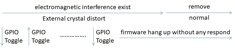
We do some validation as below:
1, Directly running TI example project from C2000ware, it still recur the hang up issue => so it should not customer firmware issue
2, Change system clock source to internal osc1, the issue do not happen => so the issue should caused by interference to external crystal
3, Stop clearing the watchdog will cause period reset => so the watchdog should be enable correctly, however it also will hang up after issue happen
4, Toggle the GPIO in firmware beginning and can check its toggle waveform for some times after electromagnetic interference => so the device should happen reset some times before totally hang up
5, Connect emulator debugging, will stop at "__asm(" ESTOP0");" in InitPll function after electromagnetic interference => so it should happen miss clock detection
void InitPll(Uint16 val, Uint16 divsel)
{
volatile Uint16 iVol;
//
// Make sure the PLL is not running in limp mode
//
if (SysCtrlRegs.PLLSTS.bit.MCLKSTS != 0)
{
EALLOW;
//
// OSCCLKSRC1 failure detected. PLL running in limp mode.
// Re-enable missing clock logic.
//
SysCtrlRegs.PLLSTS.bit.MCLKCLR = 1;
EDIS;
//
// Replace this line with a call to an appropriate
// SystemShutdown(); function.
__asm(" ESTOP0"); // Uncomment for debugging purposes
}
I suspect the firmware back to beginning and init system clock to external crystal again after device reset by electromagnetic interference affection, then device hang up because external crystal do not recover and still under electromagnetic interference.
My understand that F28035 should auto change system clock source from external crystal to internal osc1 after miss clock detection, my question is why device will not continue running by internal osc1? Why it happen reset and even hang up?
Do you have any suggestion how to set the clock and pll in firmware init rountinue maybe better to avoid the hang up issue?
1. Understand, the root cause of the issue is not customer firmware. However, we need to analyze
how the missing clock condition handled in the user application.
2. Agree, it is the crystal osc circuit that is getting impacted.
3. You are saying since WD counter is not being cleared, it should reset the device but that is not happening. OK.
4. I don’t understand what you are saying here. I see that the firmware is toggling a GPIO pin at startup. After the interference event, are you saying you see this GPIO pin toggle? After "totally hang up" if you probe the X1/X2 pins do you see any oscillation?
I suspect the firmware back to beginning and init system clock to external crystal again after device reset by electromagnetic interference affection, then device hang up because external crystal do not recover and still under electromagnetic interference.
Please probe the X1/X2 pins under this condition.
My understand that F28035 should auto change system clock source from external crystal to internal osc1 after miss clock detection, my question is why device will not continue running by internal osc1? Why it happen reset and even hang up?
It depends on how the firmware handles the missing clock condition. Please refer to sections 1.3.2.7 to 1.3.2.9 in SPRUI10.
Hi Hareesh
Regard GPIO toggle in firmware beginning, I try to explain more detail by below picture.
The electromagnetic interference will exist a period of time, we will see external crystal waveform distort and GPIO toggle (device reset) in this period. Then firmware will hang up without any respond after several times GPIO toggle, while the electromagnetic interference still exist. After remove electromagnetic interference, we can see the external crystal X1/X2 waveform seem recover normal, however the device keep hang up and also watchdog never reset. We also monitor the system clock by XCLKOUT pin, it keep output waveform but the frequency seems change randomly even after remove electromagnetic interference.
So far we just init system and handle "miss clock condition" by using TI example initsysctrl function as below, could you help advice how we can improve the handle procedure?
void InitSysCtrl(void)
{
// The Device_cal function, which copies the ADC & oscillator calibration
// values from TI reserved OTP into the appropriate trim registers, occurs
// automatically in the Boot ROM. If the boot ROM code is bypassed during
// the debug process, the following function MUST be called for the ADC and
// oscillators to function according to specification. The clocks to the
// ADC MUST be enabled before calling this function.
// See the device data manual and/or the ADC Reference
// Manual for more information.
//
EALLOW;
SysCtrlRegs.PCLKCR0.bit.ADCENCLK = 1; // Enable ADC peripheral clock
(*Device_cal)();
SysCtrlRegs.PCLKCR0.bit.ADCENCLK = 0; // Return ADC clock to original state
EDIS;
//
// Select Internal Oscillator 1 as Clock Source (default), and turn off
// all unused clocks to conserve power.
//
XtalOscSel();
//
// Initialize the PLL control: PLLCR and CLKINDIV
// DSP28_PLLCR and DSP28_CLKINDIV are defined in DSP2803x_Examples.h
//
InitPll(DSP28_PLLCR,DSP28_DIVSEL);
//
// Initialize the peripheral clocks
//
InitPeripheralClocks();
}
My understand that F28035 should auto change system clock source from external crystal to internal osc1 after miss clock detection, my question is why device will not continue running by internal osc1? Why it happen reset and even hang up?
This will happen only in the case of Case D (see page 77 of SPRUI10). Can you confirm if NMIWD is enabled in the firmware?
And may I also ask how it is better for “NMIRESETSEL” setting?
Please check if NMIRESETSEL = 1 in firmware. It is not enough to simply configure this to 1. There should be the appropriate routines in the NMI-ISR to reconfigure the PLL. Also, this doesn’t address the root cause of the issue. i.e. while it provides some containment when the system is affected due to EMI, the root cause of EMI should be addressed.
Issue is being handled offline. Will post resolution, if any.