This thread has been locked.

If you have a related question, please click the "Ask a related question" button in the top right corner. The newly created question will be automatically linked to this question.

ADS1232 How to Data Converters ?

Other Parts Discussed in Thread: ADS1232, ADS1232REF, ADS1231REF, TUSB3410

I don't know how to calculate from adc value to voltage in positive and negative

  • Hi Kittadon,

    Welcome to our forum!  Bob Benjamin answered a similar question on the ADS1232 a few months ago.  Please review this post and let us know if you still have questions:

    http://e2e.ti.com/support/data_converters/precision_data_converters/f/73/p/155786/564470.aspx#564470

  • Hi Tom

    i use  formula  equal ADC_value/(1L<<24))*(5.0/128)   

    if  negative voltage i read 19mV only 

    Regards,

  • Kittadon,

    That formula should get you very, very close, but there will be a tiny error.  The formula you use assumes a full scale unipolar value.  As this is a differential measurement, you should adjust it slightly:

    LSB = (0.5(VREF)/GAIN)/(2^23 - 1)

    As the difference between this result and the result from your formula is tiny, you must have another issue.  What is the ADC_value that is returned, and what is the actual input value?  19mV is full scale, so maybe the problem is due to common mode.  The DC value of the input must be at least 1.5V off the supply rails.

    Best regards,
    Bob B

  • Hi Bob

    Thank.

    I make circuit follow datasheets (Figure 42 )

    1.I not connect loadcell.

    2.reset and send CLK 26 th for cal offset.

    3.I read ADC value about 0xFFA0EF ,i don't no why value not equal 0x000000.

    You can tell me ? step 

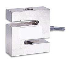
    My loadcell  ,,pull voltage is positive   ,,Press voltage is negative. 

  • Kittadon,

    If you have not connected the load cell, then the inputs are floating.  The inputs should be connected to some input voltage, otherwise the input can float to any value.  If you connect the load cell, there must be an excitation voltage to excite the bridge, with the other end of the bridge connected to ground.  The output voltage of the bridge can be connected to the ADS1232 inputs in either direction, so you don't need to have press voltage as negative ( it can also be connected to press is positive and pull is negative).  You also need to make sure that your address select pin is correct for the connected input.

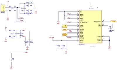
    It would be helpful to see your actual schematic, and not just a reference to a figure in the datasheet.  This would include how you are planning to connect the load cell, and to which analog input pins. 

    Best regards,

    Bob B

  • Hi Bob

    my sch

    and

    LSB = (0.5(VREF)/GAIN)/(2^23 - 1)

    so voltage = adcvalue * LSB correct?

    Thank for help.

    Best regards,

    Kittanadon


  • Kittadon,

    The formula is correct.  However there are a couple of issues with the schematic. C20 should be 0.1uF, and C16 and C18 are too large.  The common mode cap values should be 1/10th ( or smaller) as compared to the size of the differential cap.  I know the larger common mode caps help with filtering, but you will see great problems with drift and errors due to mismatch.  I would just remove C16 and C18.  Large caps will also create large delays in response.

    The rest of the schematic should be ok.  When you connect the load cell, what is the ADC value with no weight?

    Best regards,

    Bob B

  • Hi Bob

    Thank for answer.It work

    but,voltage is not correct. I measured by Meter 0. 1 mv but read from ads1232 about 0.2 mV

    Best regards,
    
    Kittanadon
  • Kittanadon,

    The accuracy of the actual measurement will be determined by the exact voltage reference value used and the accuracy of the meter you used to measure the voltage at the input.  I expect you have error in both.  Unless the meter you are using is highly accurate and is calibrated, you can only expect it to be an approximation.  You might also have a large degree of noise that is affecting the result as well.  The meter may be averaging the noise out of the measurement.

    Best regards,

    Bob B

  • how to  calibrate ADC to remove offset error  by software

  • Kittadon,

    There is a self offset calibration that can be executed via software.  This is a special pattern that is described in the datasheet.

    The other option is to subtract out the error in your software.  With no weight on the scale, the code returned should be subtracted from the result so that the software then reports this value as 0.  When you actually place a weight on the load cell, you will continue to subtract out the code result for 0 weight.  The resultant value (code_with_weight - code_no_weight) is the actual value.

    Best regards,

    Bob B

  • I am trying to reach Bob Benjamin - Is there a way I can get a hold of him ?

  • Hi Kurt,

    You found me.  If you want to start a conversation with me, click on my name and in the upper right you should see a block that includes 'Start a Conversation'.  Or you can ask to be a friend, and that will also start a conversation.

    Best regards,

    Bob B

  • Hi Bob,

    I sure happy to have found you.  I take it you know a lot about the ADS1232REF board and might be able to help me out.  We were using the ADS1232Ref board and we now are trying to use ADS1231REF in its place.  We we hook up the 1231 in place of a 1232 it does not work for us.  I have see that it is doing something, but that something looks different based on the the display.  (the only hint I have that something might not be set right on  the board)

    All the switches are thrown the same on the two boards and I have studied the specs and they seem almost identical.  I see that the gain is permanently set to 128 on the 1231 and not adjustable as it was on the 1232.  I am thinking can get the 1231 to work but am just doing something wrong.  For example I don't know how to work the 6 buttons the board has.  Maybe I should be pushing them a certain way.  The switches are all set the same between the two boards.

    What to do to get the thing to work.

  • Hi Bob,

    It was late last night and I don't remember if I gave you my correct phone number or not - So while I might be repeating myself - my phone number (correct) is: 1-507-722-1285.

  • Bob,

    Its me again on the topic of the ADS1232.  We have a successful implementation using the 1232 in Windows.  It is great. Now we are trying to use it in LINUX and can't get it to work.  If we try to connect directly using the USB to serial driver, TUSB3410, which comes with LINUX we can open the device, but we can't read and data and the device won't respond to any of our commands. 

    We also have tried to use WINE ( as windows emulator for LINUX) which will run the windows binary under LINUX - that does work either.

    Then we tried various terminal emulators and they don't work either.

    Now for the question:  Do you have any idea what might be wrong.  I imagine you know of other linux implementations - do you have anything that you could point to.  I am sure this should work.

  • Hi Kurt,

    The TUSB3410 is supported by another group.  I see that there are Linux drivers developed by a third party for this part by Brimson Labs.  You can download this file through a link on this page:

    http://www.ti.com/tool/tusb3410uartpdk

    If you still have problems with the TUSB3410 I would suggest that you post the question on the E2E Consumer and Computing forum.  You may find this post helpful:

    http://e2e.ti.com/support/interface/digital_interface/f/130/t/378125

    Best regards,

    Bob B