Other Parts Discussed in Thread: DLPC4422,
Hello, TI team!
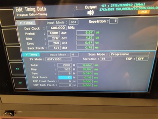
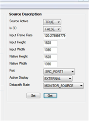
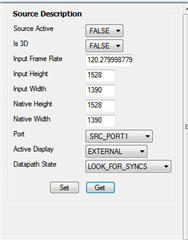
Although I have asked how to display DMD native pixels before, our supplier has tried to modify almost all timimg parameters up to now, and it still can't display correctly for 2712x1528 input signal, that is, as long as one Set XPR OFF 2WAY mode, there is no picture image.
I hope Ti's engineers can continue to help solve this problem.
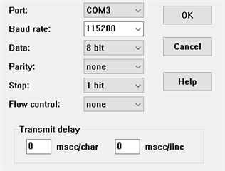
Can you give some suggestions for debugging vby1?
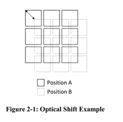
My requirement is to use native pixels, so that the DMD picture will not shake. Because I tested that if the projector is in XPR ON UHD mode or XPR ON UHD TPG mode, the pixels of DMD will shake up, down, left and right. If the projector is in XPR OFF UHD TPG mode, the pixels of DMD will not shake. So I want to use XPR OFF 2WAY mode.
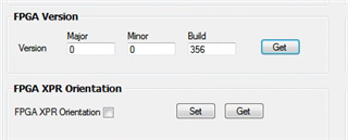
I have also tried to delete all the configuration and parameters of xrp in the engineering file, and then update ASIC flash, but as long as it is in XPR ON mode, the pixels of DMD will still shake.
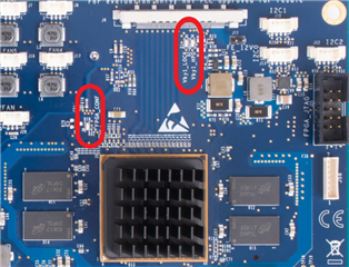
In addition, I would like to know what chip was used in the front-end board you tested before. Can this front-end board provide a purchase link or agent?