Other Parts Discussed in Thread: DLPA2005, DLP301S, DLPDLC-GUI
Hello.
I designed a custom board, DLPA2005 + DLPC1438 + DLP301S with flash memory AT25SL321(1.8V, Dialog Semiconductor) which is compatible with Winbond W25Q32.
What I did:
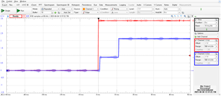
- Power on => PROJ_ON high, I2C bus low
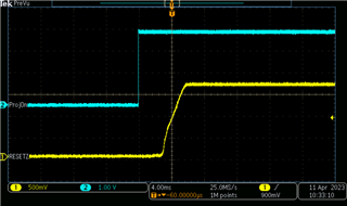
=> 1.8V, 1.1V and clock(24MHz) OK but VOFS = 4.5V, VBIAS = 4.5V, VRST = 0.5V, no SPI0 activities(just CSZ high)
=> HOST_IRQ stays high,.
I guess DLPC1438 tries to load firmware from flash before checking/configuring chipsets(DLPA2005 and DLP301S), is it true?
If so, the problem may be related to firmware loading procedure and need to be solved before double-checking my board.
Questions are:
1. When powering up(1.8V, 1.1V), does CSZ pin of SPI0 goes high and then low to try communicate with flash memory regardless of all other possible problems?
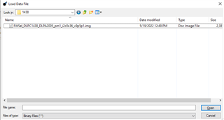
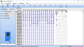
2. The firmware FWSel_DLPC1438_DLPA2005_pm1_i2c0x36_v9p5p1.img is loaded as bin via CH341A flash programmer before soldering.
But from this link, "Changing the extension from .img to .bin will likely make the firmware unusable. There are differences besides the extension for these two file types."
Solutions provided in this forum are as follows, but none of them are helpful.
- DLPDLC-GUI: cannot be used. My board is not an official EVM and does not have Cypress USB converter chip.
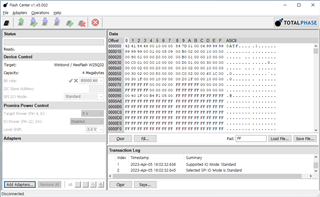
- SPI host adapter and software by Total Phase: there is no option for .img extension in Flash Center.
I could not find flash programmer that supports .img format.(let me know if you have).
If .img is different from .bin, why don't you just give firmware in .bin or .hex format?
It will make things clear and I don't need to buy another $400 flash programmer.
Thanks in advance.