


Other Parts Discussed in Thread: DLPC410, , DLPLCR95EVM, DLPA200, DLP650LNIR, DLP5500, DLP9500, DLP7000
Helpful Resources:
DLPC410 datasheet: DLPC410 DMD Digital Controller datasheet (Rev. G) (ti.com)
DLPLCRC410EVM User Guide: DLP Discovery 4100 Development Kit Software EVM User Guide (Rev. B) (ti.com)
DLP Discovery 4100 API Programmer Guide: DLP Discovery 4100 Controller Board API Programmer Guide (Rev. A) (ti.com)
If your USB is not connecting or not being recognized skip to section 3 of the guide
1. DLPLCRC410EVM: The board is not turning on; where to start debugging?
When debugging the DLPLCRC410EVM, it is recommended to start with the most common and general issues before moving on to more complex and specific ones. This approach helps narrow down the potential causes of the problem.
Check Power connector and any derivative voltages
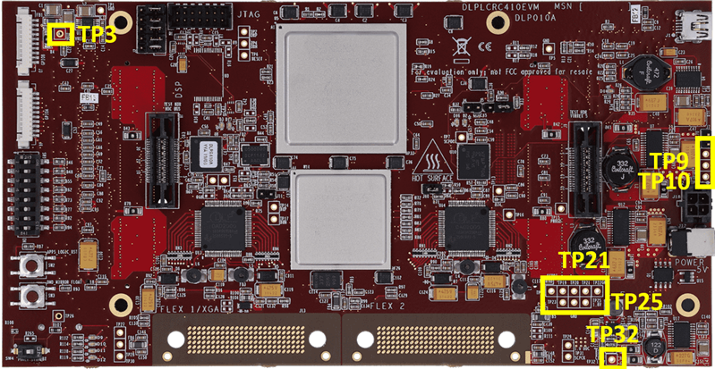
- For the DLPLCRC410EVM, the power connectors can be found at J12 and J18. Ensure that there is a 5V 6A supply connected to either J12 or J18, not both.
- Use a multimeter to check the derivative voltages by probing the test points and verifying if the voltages meet the expected values. Refer to in the EVM User Guide for helpful information on checking the power supplies. Below is a table of voltages and their corresponding test points:
|
Expected Voltage Output |
Testpoint |
|
3.3 V |
TP9 |
|
12 V |
TP21 |
|
2.5 V |
TP10 |
|
0.9 V |
TP3 |
|
1.8 V |
TP25 |
|
1.0 V |
TP32 |
After turning the power supply on, do LEDs D16 and D17 turn green after startup?
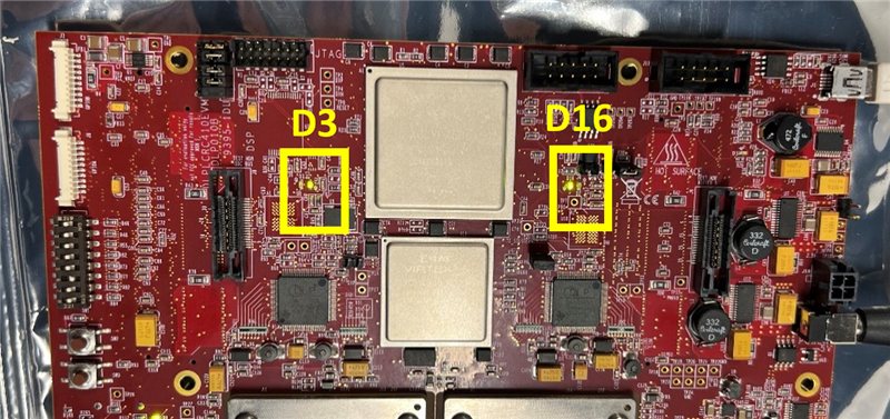
The APPSFPGA status is indicated by one green LED (D16) and one red LED (D2). While DLPC410 status is indicated by two green LEDs, D17 and D3. You will typically see D3 (green) and D2 (red) illuminate briefly on startup, before the DLPC410 and APPSFPGA are programmed. Then followed by both D17 and D16 illuminating (green LEDs) after programming is complete. Once the APPSFPGA and DLPC410 are successfully programmed, you will see a flashing green “heart beat” LED on D9 indicating that the device is correctly operating.

- D17 is Green, D2 is Red: D17 relates to the DLPC410 and shows that the DLPC410 has completed programming correctly, while D2 relates to the APPSFPGA and indicates that the APPSFPGA was not successfully programmed. This suggests that there is a problem related to the APPSFPGA. Common causes of this are listed below:
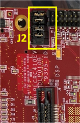
Not configuring power levels for APPSFPGA on J2: Make sure to check if J2 requires 5 jumpers to select between 2.5V or 3.3V. An image of J2 is shown below with 3.3V selected:
Corrupted PROM: If the issue persists, reprogramming the device's PROM may be necessary (view section 4).
- D3 is green and D16 is green: D16 relates to the APPSFPGA and indicates that the APPSFPGA completed programming while D3 relates to the DLPC410 and shows that the DLPC410 failed to program properly. This suggests a problem relating to the DLPC410 controller and requires further inspection, as it can be related to various factors. Common causes of this are listed below:
Corrupted PROM: Reprogramming the device's PROM may be required (view section 4).
Board turns on but when connected to the Discovery 4100 GUI it turns off
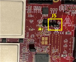
Check if LED D1 (USB enabled) turns on and check if J5 connects the FPGA to the USB.
J5 not populated: Not having a jumper on pins 1-2 of J5 can cause the GUI to not recognize the device. An image with the correct configuration of J5 is shown below
Corrupted PROM: If the issue persists, reprogramming the device's PROM may be necessary (view section 4).
There is no heartbeat on LED D9
If the heartbeat doesn’t occur it can indicate various issues, such as corrupted PROM or incorrect power connections/setup.
All the LEDs are green and there is a heartbeat on D9 but the DMD is not cycling through pre-stored patterns
- This could be related to connections on the flex cables between the controller board and the DMD
- Check the cable connections following
- If you are using the DLPLCR95EVM or DLPCR95UVEVM and see consistent horizontal lines on the DMD that do not go away, even when cycling through test patterns, ensure that J10 has a jumper installed
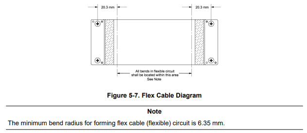
- Electrical malfunctions can occur by stressing the flex cable connecting the DMD circuit board to the DLPC410 controller circuit board. Stressing the flex cable can be caused by:
- Bending the cable outside the area identified in Figure 5-7 (within 20.3 mm of connector plate centers).
- Repeatedly bending the flex cable(s) where the bend radius is less than 25.4 mm.
- A single bending of the flex cable(s) where the bend radius is less than 6.35 mm.
- Check the cable connections following
- When Tightening screws for the flex cable it is recommended you place the insulated backer plate on the other side of the DMD/Controller board from the flex side with connection pins and carefully tighten the screws. Alternate tightening the screws from side to side until the screws are firm, but not overtightened (SCREW TORQUE REQUIREMENT: 6-8 in-lb [0.7-0.9 N-m]).
- Verify that the flex cable does not have any missing C-springs. If any C-springs are missing or if the connection is loose, it can cause abnormal behavior of the DMD.
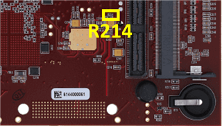
- This could also be due to incorrect voltages on Vbias (R92), Voffset (R214), or Vreset (R88)
- We can check this by probing voltages with a multimeter on the corresponding resistors found in the schematic and verifying the voltages are in the expected range found in the DLPA200 datasheet
|
Parameter |
min |
typ |
Max |
unit |
|
Vbias |
25.5 |
26 |
26.5 |
V |
|
Voffset (DLP9500,DLP5500,DLP650LNIR) |
8.25 |
8.5 |
8.75 |
V |
|
Voffset (DLP7000) |
7.25 |
7.5 |
7.75 |
V |
|
Vreset |
-25.5 |
-26 |
-26.5 |
V |

Previous E2E threads:
2. DLPLCRC410EVM: Discovery 4100 Explorer installation error, DDC4100.ocx
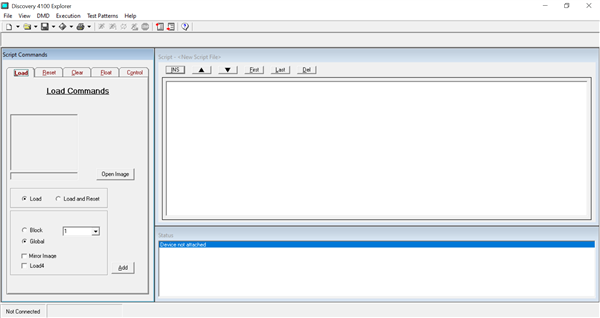
This error tends to occur when attempting to install the Discovery 4100 Explorer GUI software on Windows 10+. This can result in error messages such as "Error running Post Install Script. The installation may have not completed “The module ‘DDC4100.ocx’ failed to load.”
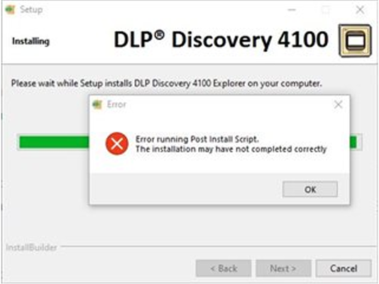
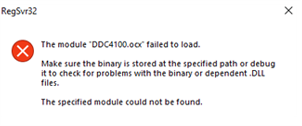
Try to “uninstall” the program if it shows up as installed, then search for 2010 vcredist_x86.exe from Microsoft. Once you install 2010 vcredist_x86.exe, reboot, and attempt to install the GUI once again.
Previous E2E threads:
3. DLPLCRC410EVM: Discovery 4100 Explorer not recognizing USB
A common issue with the Discovery 4100 Explorer GUI is the software's failure to recognize the USB connection. The most common cause is improper setup of the EVM board, often due to not enabling the USB connection on J5.
If the connection is correct and the GUI still does not recognize the USB, it is usually because the D4100 Driver has not been downloaded. To address this issue, follow , which provides instructions for downloading the D4100 Driver.
If problems persist even after downloading the D4100 Driver, it is possible that the VID or PID of the device is incorrect, although this is rare. To view the VID and PID of the device, follow these steps:
- Go to Device Manager and find the TI D4100 Explorer
- Open the Properties of the device
- Go to the details tab
- check the hardware IDs
- The VID should read 0451
- The PID should read AF33
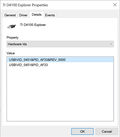
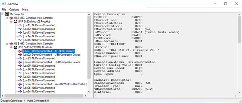
You can also use USB viewer software like USB View to obtain the same information, which will be listed under the idVendor (0x0451) and idProduct (0xAF33)
4. Corrupted PROM, how to load firmware on to the DLPC410 and APPSFPGA
If the FPGA or controller has a corrupted PROM, the only way to fix it is to reload the firmware onto the DLPC410 and the APPSFPGA. This requires programming the devices over the JTAG interface using a USB-JTAG cable supported by the AMD Xilinx ISE Impact Tool. The procedure described below was tested using the ISE Impact Tool version 14.1 with a Digilent JTAG-HS2 programmer.
The DLPC410 SPI Flash MCS and bit files to use in this procedure is found here: DLPR410
- Open up the Impact application.
- Power on the DLPLCRC410EVM and connect the JTAG-HS2 programming cable to JTAG Header H1 and then to the PC that you have the IMPACT Tool installed on.
- Once the program is open, select either to start a new project
- Select Configure device using Boundary-Scan (JTAG), which initializes the JTAG chain.
- Program the APPSFPGA
- Select the FPGA device. Select add SPI/BPI PROM.
- Add the .mcs file for the FPGA. Select SPI PROM and S25FL032P with a data width of 1 and press OK.
- Select Yes to ignore the data width warning.
- To program the device through IMPACT Tool, right-click on the FLASH and click Program. User can also select Program under Impact Processes on the bottom left of the IMPACT Tool.
- The FPGA programs and reports “Program Succeeded” in the IMPACT Tool.
- Program the Controller
- Select the controller device. Select add SPI/BPI PROM.
- Add the .mcs file for the controller. Select SPI PROM and S25FL032P with a data width of 1 and press OK.
- Select Yes to ignore the data width warning.
- To program the device through IMPACT Tool, right-click on the FLASH and click Program. User can also select Program under Impact Processes on the bottom left of the IMPACT Tool.
- The controller programs and reports “Program Succeeded” in the IMPACT Tool.
- Power down the DLPLCRC410EVM and remove the JTAG-HS2 programmer.
