This thread has been locked.

If you have a related question, please click the "Ask a related question" button in the top right corner. The newly created question will be automatically linked to this question.

DLPA2005: LED activation causes fault interrupt and shutdown

Part Number: DLPA2005
Other Parts Discussed in Thread: DLPC3420, DLP160AP

We are working on a custom board featuring the DLP160AP chipset (DLPC3420+DLPA2005). 

We have a fully functional design which does not utilize the internal VLED driver and uses external illumination.

On a new prototype, we are attempting to use the VLED regulator to drive a single illumination LED. The system boots normally and displays the splash screen for a few 100s of milliseconds. However. when the LED1 is enabled (LED_SEL0 is asserted by the DLPC automatically), a fault is triggered by the DLPA2005 within about 17 us after LED activation, as signified by the PARKZ/INTZ line being pulled low (see image below) and the system goes into fast park, following after about 34 us by RESETZ being pulled low causing the system to shutdown. 

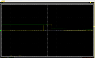
(LED_SEL0 yellow, PARKZ green)

We are using a 10 Ohm resistor in place of the LED for safe testing. After measuring the VLED line, we have found that the VLED voltage rises above 5.4V which likely triggers the LED overvoltage fault (LED_OVP) in the DLPA (see image below).

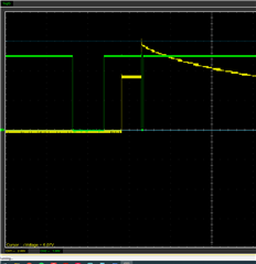
(Yellow: VLED, Green: RESETZ)

Following this, we have attempted 2 I2C control commands to prevent this with no viable results.

  • Issuing Write RGB LED Enable (52h) before the automatic LED activation does not prevent the controller from activating the LED_SEL0 line. The LED is activated later regardless and despite the DLPC acknowledging the command.
  • Write RGB LED Max Current (5Ch) does appear to prevent the VLED overvoltage. After the LED is activated by the DLPC (LED_SEL0 is pulled high), VLED now falls and holds stable regulation at a lower voltage such that the LED (in this case, resistor) current is correct according to the specified value (about 200 mA). Voltage measured at RLIM was 8 mV, in accordance with 200 mA). Despite no overvoltage being visible, the DLPA still issues the interrupt in identical manner and puts the system into fast park shutdown.

We have verified that all other output voltages of the DLPA  (1.1V, 1.8V, 2.5V,3.3V, 6.6V and DMD operating voltages) are stable.

My questions are:

  1. Is VLED_OVP interrupt masked or unmaksed by the DLPC firmware? While the interrupt is masked in the DLPA by default, I have no information whether the DLPC firmware modifies this. Would this condition cause system reset in this manner? 
  2. Is it possible to extract the fault code from the DLPA using the DLPC firmware? We can access the fault/interrupt register in the DLPA externally, however this requires tapping a standalone microcontroller into the DLPA's SPI line. Determining the origin of a fault should be an important part of the system.
  3. Is it possible to mask the DLPA interrupts using the DLPC firmware? Once again, we could access the mask register with an external microcontroller but this is not desirable
  4. Are there any conditions other than VLED_OVP, related to the VLED regulator which can cause the DLPA to output an interrupt via the INTZ pin?
  5. Is it possible to set the default LED max currents in the firmware persistently? Otherwise this requires the host to issue an I2C command in a relatively short time frame every time after the DLP system boots and before the LEDs are activated shortly afterwards. I would imagine that this is a constant value somewhere within the firmware ROM. While the DLPC offers I2C commands for writing to Flash, without knowing it's address we cannot modify it. Are the user-modifiable parts of the firmware (such as configuration, splash screens, etc.) documented somewhere?
  • Hello Martin,

    Welcome back to the E2E forum. Thank you for your continued business. We are looking into your five questions and will have a response within the next few days.

    Best,

    Maxine

  • Hello Martin,

    1. The VLED_OVP interrupt is unmasked by the DLPC3420 firmware. When overvoltage protection is triggered the system resets.

    2. It is not possible to extract the fault code from the controller, as the system will just shut down, including I2C communication.

    3. It is highly not recommended to mask the interrupts from the DLPA2005. It is not a supported feature.

    4. There are a number of faults that cause an interrupt through INTZ. The interrupts are listed below. See the DLPA2005 Data Sheet for further details about the interrupt registers and corresponding interrupt mask registers.

    5. Yes, maximum LED currents can be set. Use the I2C to send the command each time it boots. 

    In addition, please reconfirm that the 10ohm resistor you are using as a load is a power resistor that is the correct value needed for your system.

    Best,

    Maxine

  • Thank you, I think I've been able to find the tool, however I cannot find any documentation for how to use it. It looks like there is no option to create a new project, only open an existing one. It seems that it is oriented towards the evaluation boards, however we are using a custom board. Any advice would be appreciated.

  • Hello Martin,

    A small correction, please use I2C directly to send the command to set the maximum current limit. This is the most straightforward method.

    Best,

    Maxine

  • Ok, so does this mean there is now way to change the default setting? Does the max current need to be changed every time during startup? That does not seem very stable, there is only a small time window when the command can be issued before the VLED driver would overshoot and trigger the interrupt with the default large current. 

  • Hello Martin,

    I am currently consulting with our system experts to get you the most accurate information. On our systems, we generally use the PMIC faults as a way of protecting the hardware and do not support illumination that exceeds the PMIC specs.

    Best,

    Maxine

  • Hello Martin,

    Thank you very much for your patience and I do apologize for any confusion. Our expert response is that we do not support configurations that exceed PMIC specs due to the present danger of irreversibly damaging the driver. Thus, we cannot give you any sanctioned recommendations regarding changing maximum current limits. In addition, please be aware that your dummy load is not a power resistor so it may not take heat well over time. 

    Best,

    Maxine

  • Hello Maxine,
    I think you mistunderstood our intent. We want to decrease the default LED driving current, not increase the current limit. The LED max driving current is set to a value which is too high for our system. We can change the maximum driving current with I2C after the system boots, however we would like to change the default value (which is likely saved somewhere in the firmware file), such that it would not be required to change it manually after every system boot.

  • Hello Martin,

    Thank you for clarifying. What kind of external illumination are you using? Is the driving current exceeding your system specs for all three colors?

    Best,

    Maxine

  • Hello Martin,

    I have sent you a friend request. Please accept it and we will discuss moving forward there.

    Best,

    Maxine

  • Thank you Maxine, I've accepted. To clarify, the illumination is still in development and not final. We will be using a single monochromatic medium power LED (under 200 mA). The problem is, that after boot-up, your firmware automatically sets the DLPA driving current to 0x0FF which corresponds to about 630 mA of driving current with the recommended 39 mOhm sense resistor. As mentioned above, we can change this to a different value after the system boots using I2C commands, but this would have to be done after every system boot, we would like to change the default setting permanently, which (I expect) should as trivial as changing a data byte (default value) stored in the firmware image, if we knew the address (which we don't since the firmware is closed source).

    Additionally, regarding the other issues mentioned in this thread, it seems that the fault was once again a system undervoltage, even though we were unable to observe the conditions as specified in the datasheet (we never measured a voltage drop below 2.7V whereas the datasheet specified a default 2.3V threshold - this is variable, perhaps the firmware changes this after boot?), we have changed the main power supply to a stronger one and added more decoupling and the system is now stable and runs fully without issue with the illumination running. Our initial testing also showed that, contrary to what you claimed before, the system will run even with the illumination LED disconnected, the VLED driver will reach the overvoltage threshold and stop, without triggering a system reset (the VLED OVP interrupt seems to be masked in the DLPA). We will will have to perform some more testing with another board to be sure that this is indeed the correct behavior and not a glitch. 

  • Thread moved offline.